Stereoscopic vision flickering perception test device

A test device and stereo vision technology, applied in the application field of electronic technology, can solve the problems of test research, inability to conduct test research on flicker perception of 3D display equipment, and inability to test flicker perception, so as to achieve accurate test results

Inactive Publication Date: 2012-06-20
SOUTHEAST UNIV
View PDF5 Cites 7 Cited by
  • Summary
  • Abstract
  • Description
  • Claims
  • Application Information

AI Technical Summary

Problems solved by technology

In these technologies, since two images are presented to the left and right eyes, the principle of flicker perception produced by flickering separately is different from the flicker perception obtained when two eyes watch the same image at the same time. Conduct flicker perception test studies under these conditions
[0004] In addition, the current technology of presenting different images to the left and right eyes by time separation or space separation, and forming a three-dimensional image through the fusion of the human brain breaks the coordination mechanism of the adjustment function of the single eye and the convergence function of the two eyes. The perception situation cannot be tested with the existing stroboscope
[0005] To sum up, due to the development of 3D display technology, the existing stroboscopes cannot present images with different flicker frequencies, brightness, colors, and flicker modulation depths to both eyes, and cannot measure the effects of breaking the normal monocular adjustment and binocular convergence. Flicker perception when presenting stereoscopic images under the condition of coordination mechanism, so it is impossible to test and study the stereoscopic flicker perception of existing 3D display devices

Method used


Image

  • Stereoscopic vision flickering perception test device
  • Stereoscopic vision flickering perception test device
  • Stereoscopic vision flickering perception test device

Examples


Embodiment Construction

[0037] The technical solution of the present invention will be described in further detail below in conjunction with the accompanying drawings.

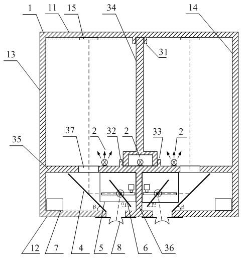
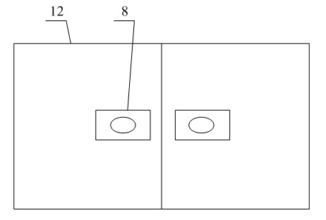
[0038] Stereo vision flicker perception testing device of the present invention comprises casing 1, light source 2, fixed reflector 4, movable reflector mechanism, controller 7 and observation window 8, and casing 1 is the cube that top is movable cover plate, and casing The inner surface of 1 is covered with non-reflective material, and the light insulation device arranged between the front facade 11 and the rear facade 12 of the box body 1 divides the box body 1 into two symmetrical darkrooms. The light insulation device includes a movable light insulation board 34. Transverse light-insulating plate 35 and longitudinal light-insulating plate 36. The movable light-insulating plate 34 includes a vertical straight plate and an inverted U-shaped plate arranged at one end of the longitudinal straight plate. The opening side of the invert...


PUM


Abstract

The invention relates to a stereoscopic vision flickering perception test device; parameters are input at a man-machine interaction interface and are computed by a microprocessor, two paths of stepping motors are driven, the angle and the position of a movable reflector are adjusted, an image can be taken on in a left eye and a right eye correctly, and a stereoscopic image is formed through vision fusion of a tester, and a flickering perception test is performed under illumination of a light source. The inner wall of a box body in the invention is made of a non-glaring material, the inside ofthe box body is illuminated by a full-color light-emitting diode, so that flickering perception test can be realized under a single light source and different light source illumination in double eyes. In the invention, the flickering frequency, phase difference, brightness, color, light and dark modulation depth and the like of the light source can be adjusted as required, and the test device overcomes the disadvantages that the existing stroboscope can not test the flickering perception in stereoscopic display equipment, can not test fusion condition of two eyes for different flickering lights, can not test the flickering perception condition when a single-eye adjusting position is inconsistent with a convergence point of two eyes and can comprehensively and scientifically perform flickering perception test and research of human eyes.

Description

technical field [0001] The invention belongs to the application field of electronic technology, and in particular relates to a stereoscopic vision flicker perception testing instrument. Background technique [0002] At present, the human eye flicker perception test generally uses a stroboscope as a measuring instrument. The stroboscope can control the light source to flash quickly at a specific frequency, so as to measure the flickering feeling. This type of instrument has a simple structure and a single function. It can only test the impact of the flicker frequency on the flicker perception ability of the human eye when two eyes look at the same light source, but cannot test the flicker perception of the two eyes under different light sources, and cannot modulate the light source. Color, Modulation Depth, etc. Only the human eye's perception of simple flickering light sources can be measured. [0003] At present, 3D display technology is developing rapidly, and various d...

Claims


Application Information

Patent Timeline
Patent Type & Authority Applications(China)
IPC IPC(8): A61B3/08A61B3/06A61B3/02
Inventor 陈磊李晓华夏振平
Owner SOUTHEAST UNIV
Why Eureka
Try Eureka