Shutter-based stroboscope

a stroboscope and shutter technology, applied in the field of stroboscopes, can solve the problems of limited distance usage of flash-based stroboscopes, inability to perform optimally of electronic stroboscopes, and inability to optimize the performance of flash-based stroboscopes

Inactive Publication Date: 2010-04-01
MURTONEN SALOMO
View PDF10 Cites 6 Cited by
  • Summary
  • Abstract
  • Description
  • Claims
  • Application Information

AI Technical Summary

Problems solved by technology

An electronic stroboscope has numerous limitations.
For instance, in bright background light, a flash-based stroboscope cannot perform optimally because the bright backlight fades out the

Method used


Image

  • Shutter-based stroboscope
  • Shutter-based stroboscope
  • Shutter-based stroboscope

Examples


Embodiment Construction

[0016]Now, exemplary embodiments of the present invention will be described in more detail with reference to the accompanying drawings.

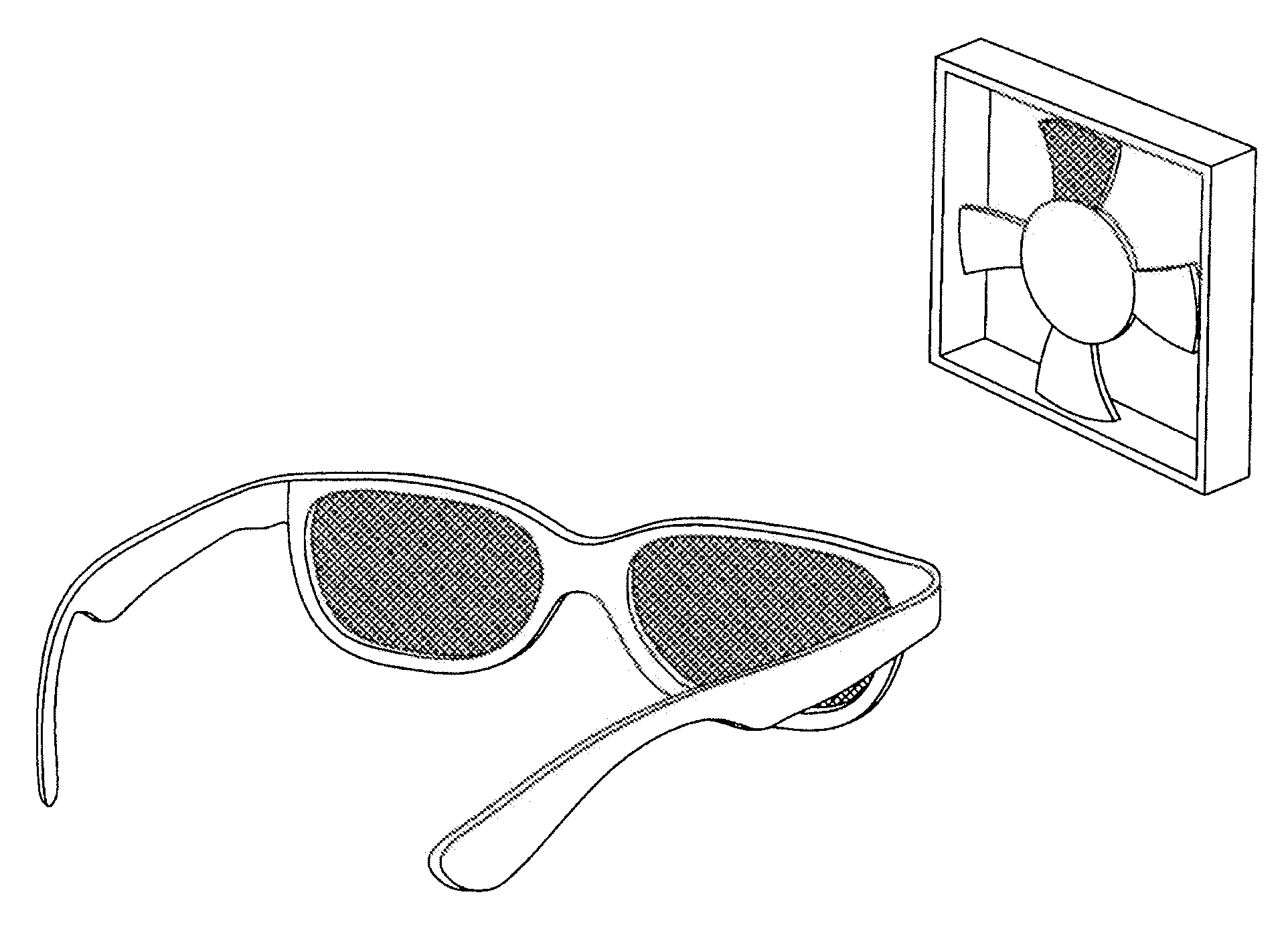
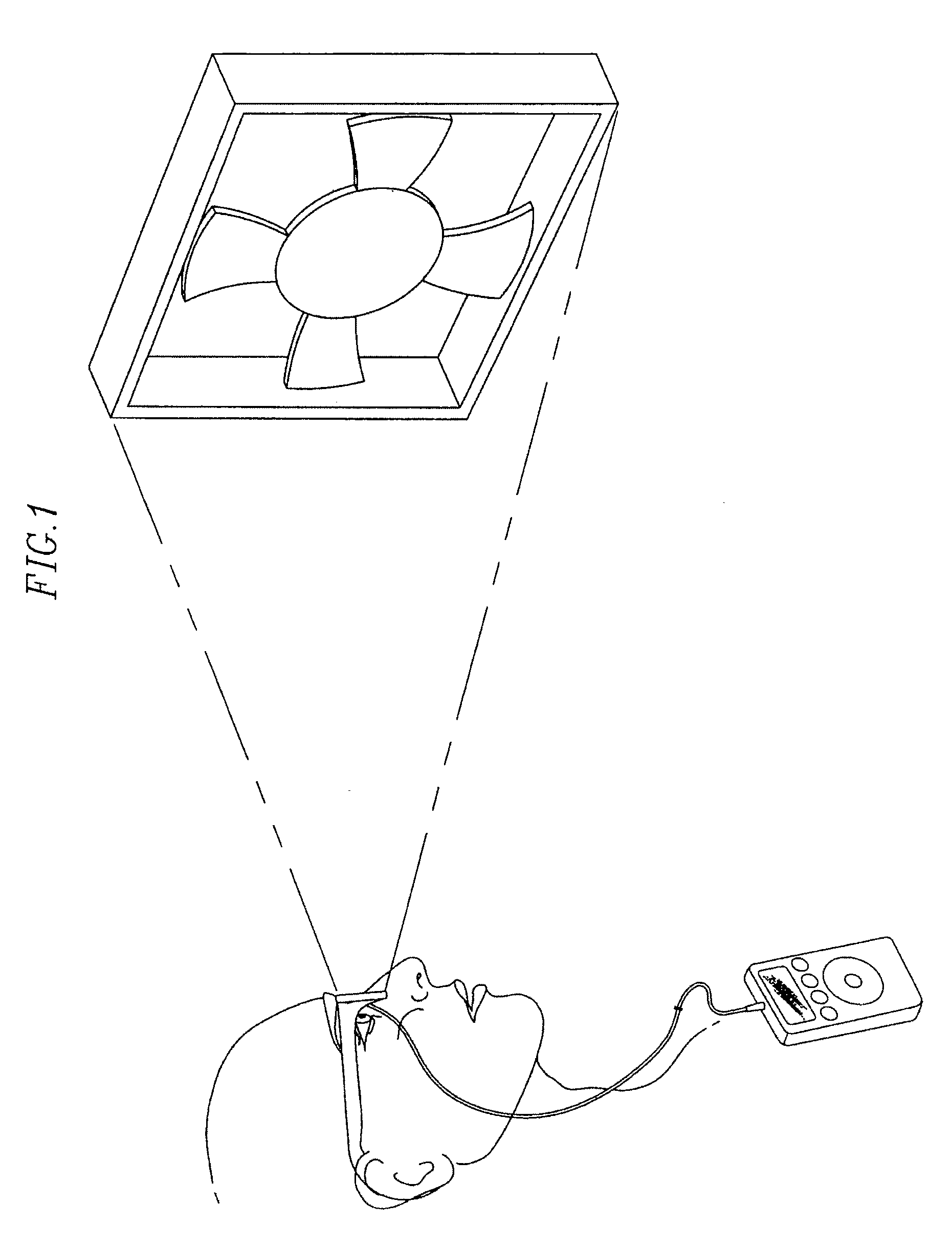
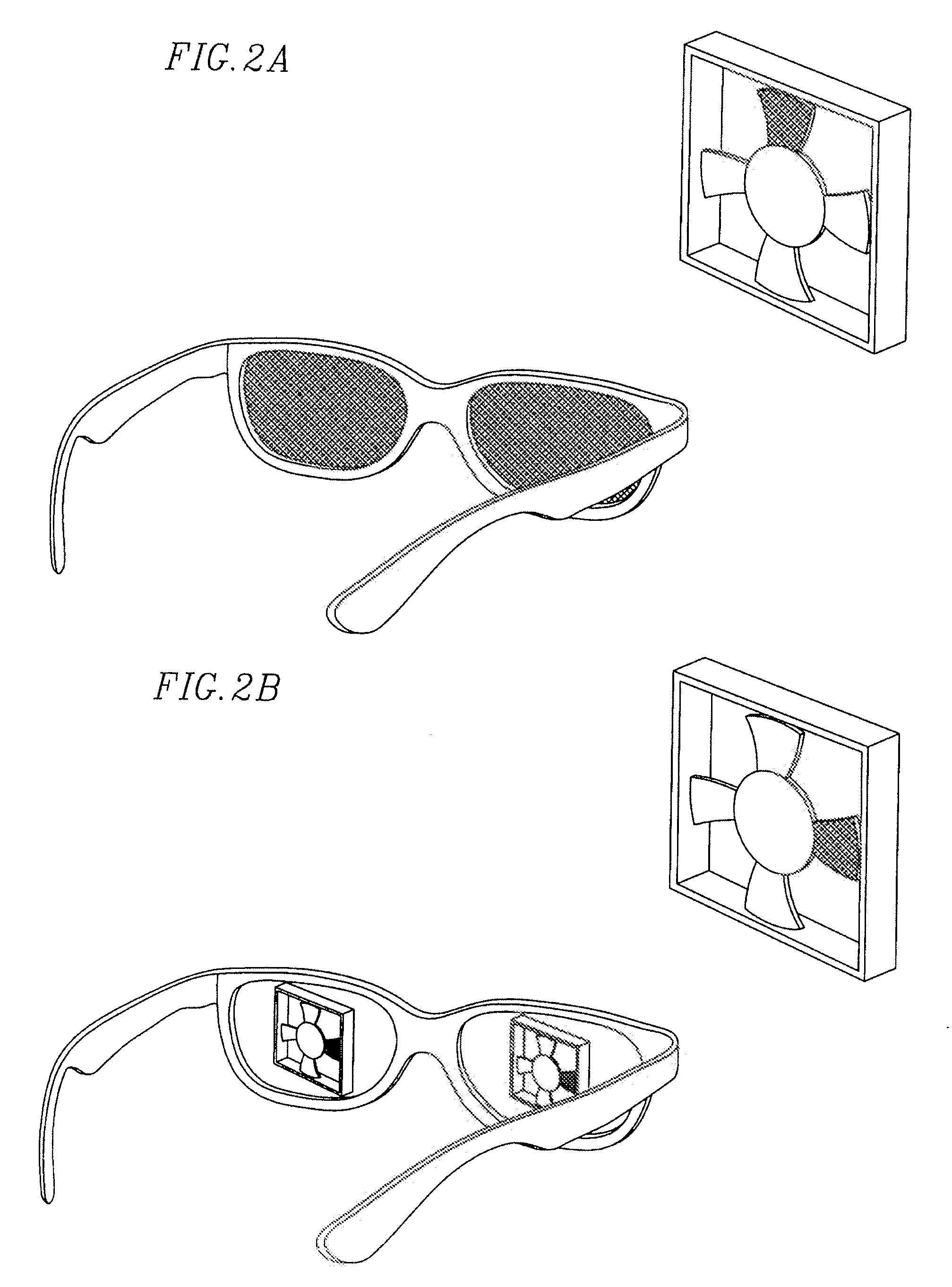
[0017]A shutter-based stroboscope is provided according to one embodiment of the present invention. The shutter-based stroboscope typically uses natural background light (the brighter the light, the better the result). Most speed or vibration testing takes place during daytime or in well-lit indoor facilities. This is a suitable condition for a shutter-based stroboscope. The shutter-based stroboscope also saves energy (only a small low-power battery is typically required). In addition, the shutter-based stroboscope may use a pocketsize, handheld controller, which is lightweight and easy to carry around. In other embodiments, the size and mobility of the controller may vary. For example, the controller may be mounted in a big system chassis.

[0018]The shutter-based stroboscope functions as easily for long distance observations as it does for short dist...


PUM


Abstract

Traditional stroboscopes use either a perforated rotating disc or intermittent lighting to alternately occlude or highlight a particular scene at periodic intervals. The embodiments of the present invention are directed to a shutter-based approach, where an optic (such as eyeglasses, binoculars, or a magnifying glass) is equipped with a shutter (such as a liquid crystal display) to periodically occlude the vision of a user through use of a handheld controller to regulate the shutter speed.

Description

CROSS-REFERENCE TO RELATED APPLICATION(S)[0001]This application claims priority to and the benefit of U.S. Provisional Application No. 61 / 100,762, entitled “Shutter-Based Stroboscope,” filed Sep. 29, 2008, the entire content of which is incorporated by reference herein.BACKGROUND OF THE INVENTION[0002]A stroboscope is an instrument used to make a cyclically moving object of uniform speed appear to be slow moving or stationary. A basic stroboscope is made of a rotating disc with evenly spaced holes placed in the line of sight between the observer and the moving object. The rotating disc exposes the moving object for brief periods when a hole in the disc lines up with the observer's line of sight. The rotating speed of the disc adjusts so that it synchronizes or nearly synchronizes with the movement of the observed system by exposing the object at moments when the object is presenting itself in roughly the same orientation to the observer. Perfect synchronization makes the object appe...

Claims


Application Information

Patent Timeline
IPC IPC(8): G02F1/01
CPCG03B15/05G01P3/40
Inventor MURTONEN, SALOMO
Owner MURTONEN SALOMO
Why Eureka
Try Eureka