
Halyard system for a flag pole

a flag pole and halyard technology, applied in the field of flag poles, can solve the problems of excessive components, high cost of internal pulley systems, and theft of external pulley systems, and achieve the effect of less cost for the manufacturer

Active Publication Date: 2007-01-11
COLONIAL DISCOUNT FLAG & FLAGPOLE
View PDF28 Cites 21 Cited by
  • Summary
  • Abstract
  • Description
  • Claims
  • Application Information

AI Technical Summary

Benefits of technology

[0008] It has been recognized that it would be advantageous to develop a simplified halyard system for suspending a peripheral side of a flag adjacent to a flag pole that is less costly for the manufacturer and the end user.
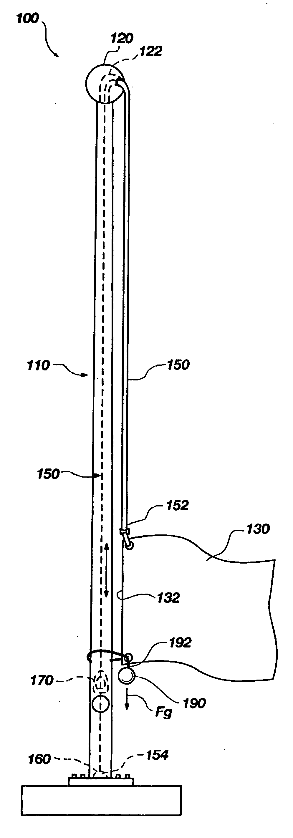
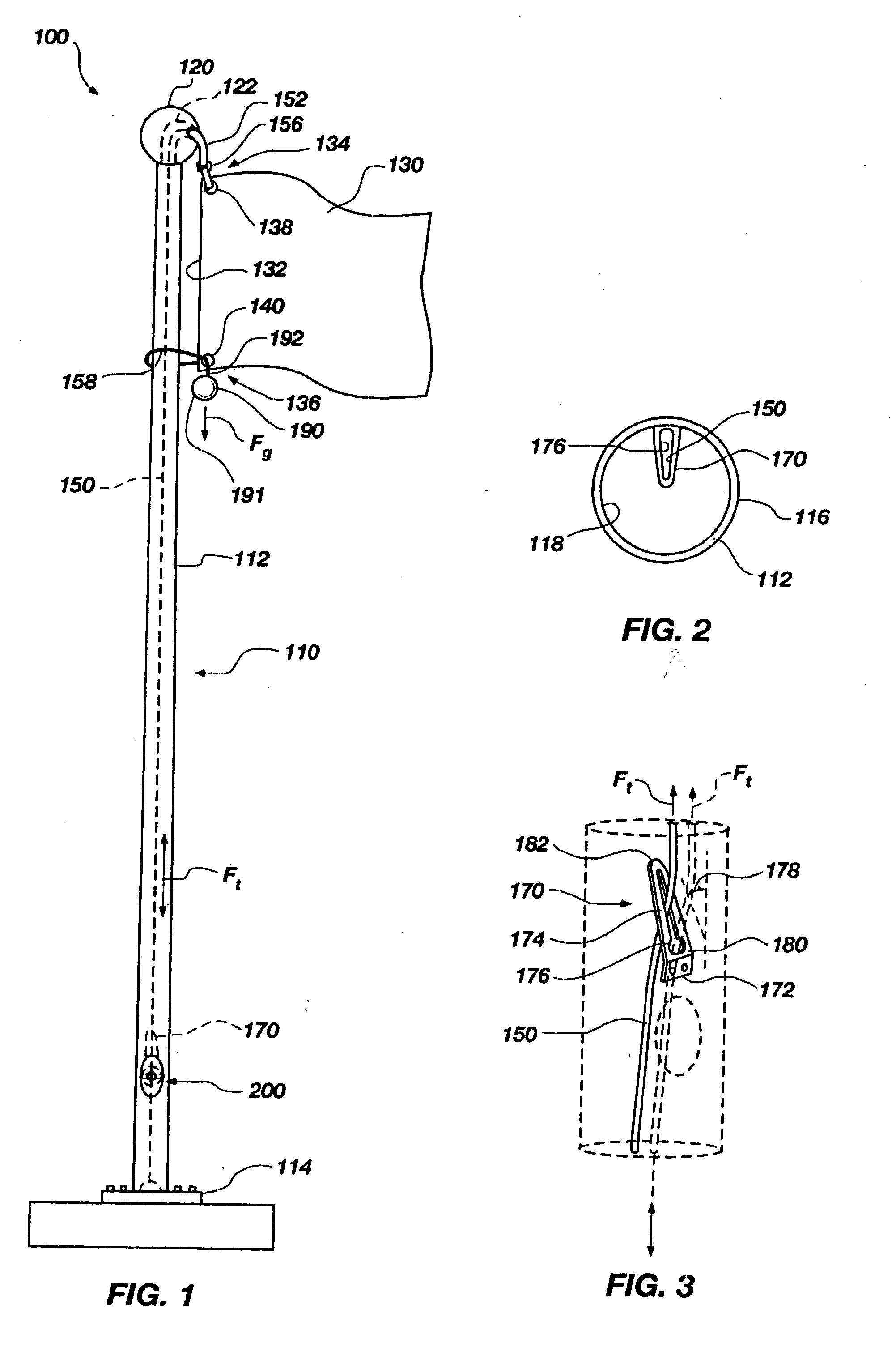
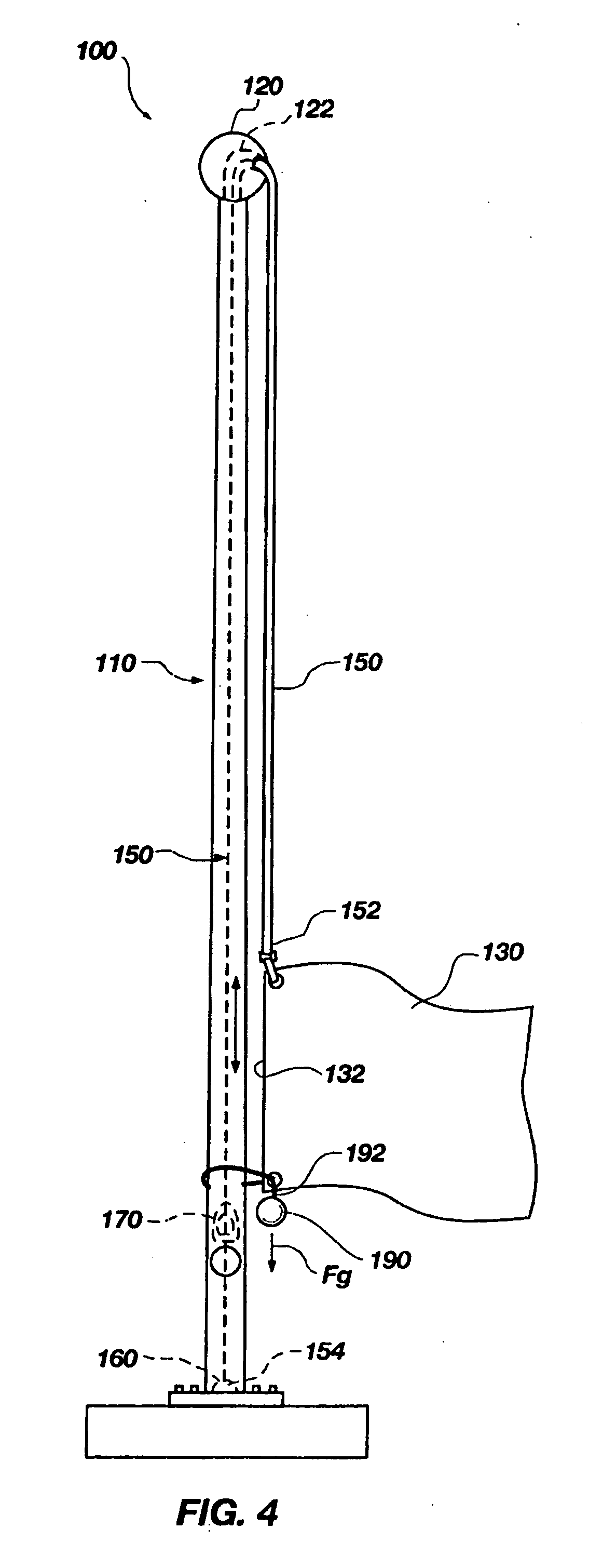
[0009] The present invention relates to a method and apparatus for providing a halyard system configured to suspend a flag on a flag pole. The halyard system includes a holding member, a line member and a weighted-down mass structure. The holding member is coupled to the flag pole. The line member is operatively coupled to an upper side portion of the flag and extends through an upper portion of the flag pole and is operable to be removably coupled to the holding member. The weighted-down mass structure is operatively coupled to a lower corner of the flag adjacent the pole and is operable to freely hang from the lower side portion of the flag. With this arrangement, the weighted-down mass structure places tension on the line member and a peripheral side of the flag so as to substantially maintain the peripheral side of the flag in a suspended position along side the flag pole.

Problems solved by technology

However, external pulley systems pose problems with theft and exposure to the elements in the environment.
Although internal pulley systems deter theft and exposure to the elements, such internal pulley systems are typically much more expensive than the external systems as the internal systems often require more advanced pulley systems to suspend the flag along the outside of the pole.
However, this locking mechanism is expensive and requires excessive components along with the pulley system to properly function.
Although the spring-biasing cam locking mechanism is relatively inexpensive, over time the line will experience wear against the ruff surface of the cam and components of the spring-biasing cam locking mechanism may break down and degrade.
Further, the spring-biasing cam locking mechanism is operated with a pulley system, which adds cost to the manufacturer and the end user.
Another problem with internal pulley systems is the necessity of having an access opening with a locking door to allow both authorized access and prevent unauthorized access to the halyard system.
These many components employed for the locking door will often weather over time from exposure to the elements and are rather unsightly to look upon.

Method used


Image

  • Halyard system for a flag pole
  • Halyard system for a flag pole
  • Halyard system for a flag pole

Examples


Embodiment Construction

[0022] Reference will now be made to the exemplary embodiments illustrated in the drawings, and specific language will be used herein to describe the same. It will nevertheless be understood that no limitation of the scope of the invention is thereby intended. Alterations and further modifications of the inventive features illustrated herein, and additional applications of the principles of the inventions as illustrated herein, which would occur to one skilled in the relevant art and having possession of this disclosure, are to be considered within the scope of the invention.

[0023]FIG. 1 illustrates a halyard system 100 for suspending a flag 130 to a vertically standing flag pole 110. Such a flag 130 is typically rectangular in shape and includes one peripheral side 132 configured to be suspended along side the flag pole 110 to properly display the flag 130. Suspension of the flag 130 along the peripheral side 132 can be employed by including a first eyelet 138 and a second eyelet ...


PUM


Abstract

A method and apparatus for providing a halyard system configured to suspend a flag to a flag pole. The halyard system includes a holding member, a line member and a weighted-down mass structure. The holding member is coupled to the flag pole. The line member is operatively coupled to an upper side portion of the flag and extends through an upper portion of the flag pole to be removably coupled to the holding member. The weighted-down mass structure is operatively coupled to a lower side portion of the flag and operable to freely hang from the lower side portion of the flag. With this arrangement, the weighted-down mass structure is operable to place tension on the line member and a peripheral side of the flag so as to substantially maintain the peripheral side of the flag in a suspended position along side the flag pole.

Description

BACKGROUND OF THE INVENTION [0001] 1. Field of the Invention [0002] The present invention relates generally to flag poles. More particularly, the present invention relates to a simplified halyard system for a flag coupled to a flag pole. [0003] 2. Related Art [0004] Halyard systems for hoisting and lowering flags to flag poles are well known in the art. Flag poles extending upward 20 ft. and taller typically include halyard systems having various pulleys at the upper and / or lower ends of the flag pole with a flag line coupled to such pulleys and attached to a peripheral side of the flag. Halyard systems utilizing pulleys are known to be located internal and external to the flag pole with various manually accessible locking mechanisms for holding the flag in a suspended position with respect to the flag pole. However, external pulley systems pose problems with theft and exposure to the elements in the environment. Although internal pulley systems deter theft and exposure to the eleme...

Claims


Application Information

Patent Timeline
IPC IPC(8): G09F17/00E04H12/32
CPCE04H12/32Y10T24/3918G09F17/00
Inventor SWENSON, PAULDIEKEY, MARKVAN SCHELT, JACK
Owner COLONIAL DISCOUNT FLAG & FLAGPOLE
Learn More