Heat exchanger with plate projections

a heat exchanger and plate technology, applied in indirect heat exchangers, lighting and heating apparatuses, laminated elements, etc., can solve the problems of system failure, difficult to remove residues in flow channels, etc., and achieve the effect of optimizing heat exchanger strength and heat exchange efficiency

Inactive Publication Date: 2007-01-11
MODINE MFG CO
View PDF15 Cites 29 Cited by
  • Summary
  • Abstract
  • Description
  • Claims
  • Application Information

AI Technical Summary

Benefits of technology

[0011] In still another form of this aspect of the present invention, the number, configuration and arrangement of the first and second projections are selected to optimize heat exchanger strength and heat exchange efficiency.

Problems solved by technology

However, such inserts often can cause difficult to remove residues to remain in the flow channels, including, for example, fine metallic chips that form during production of the internal inserts.
If such residues reach the oil loop, for example, they can lead to failure of the system.

Method used


Image

  • Heat exchanger with plate projections
  • Heat exchanger with plate projections
  • Heat exchanger with plate projections

Examples


Embodiment Construction

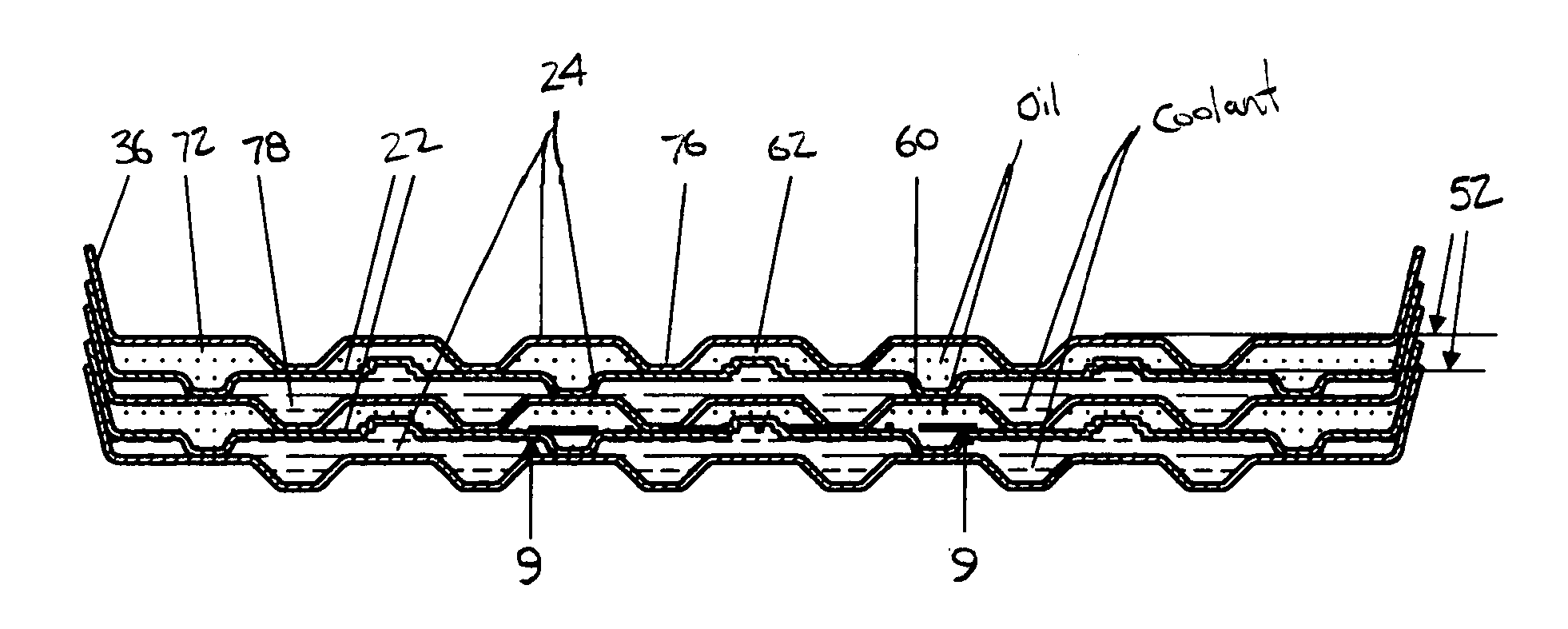
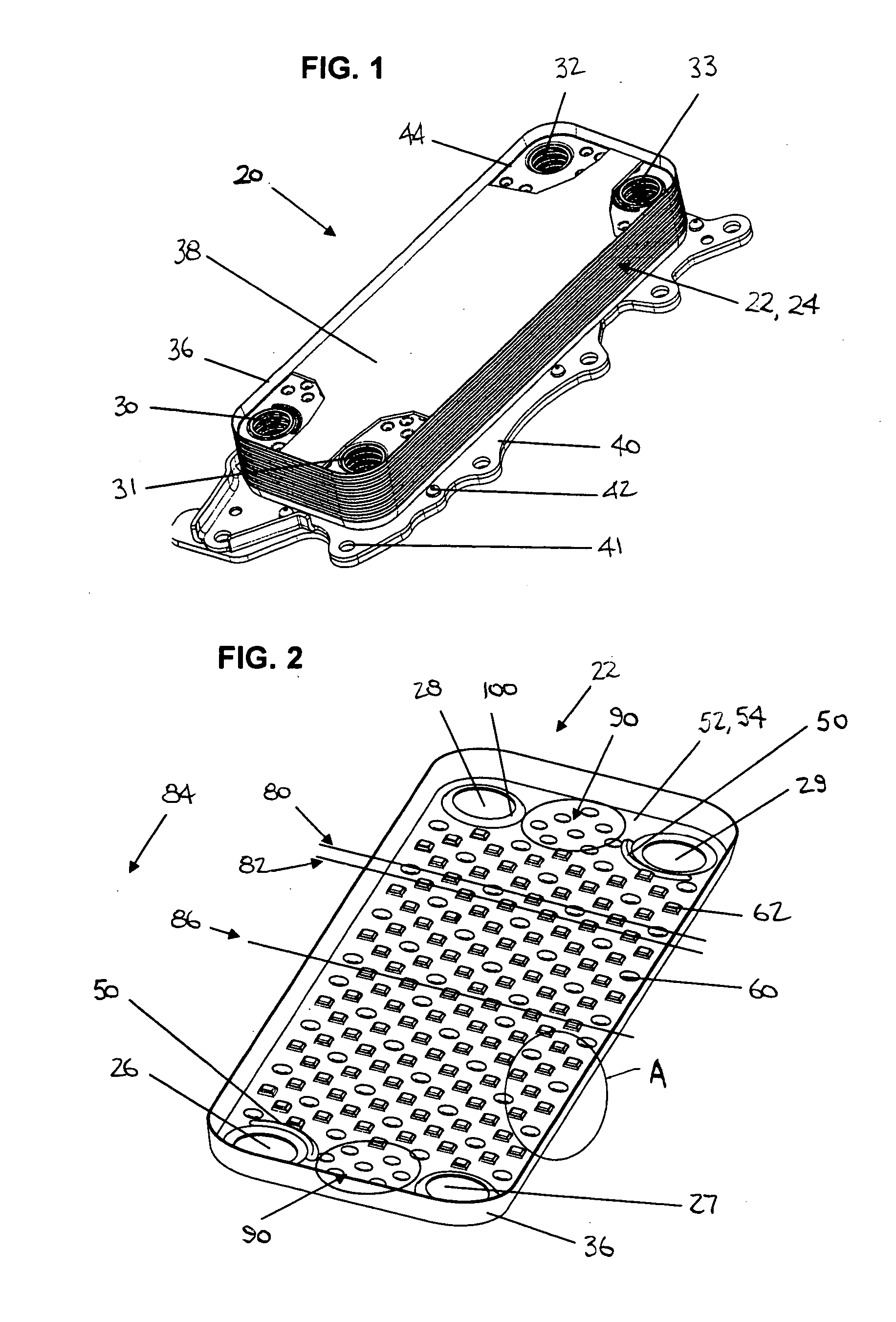
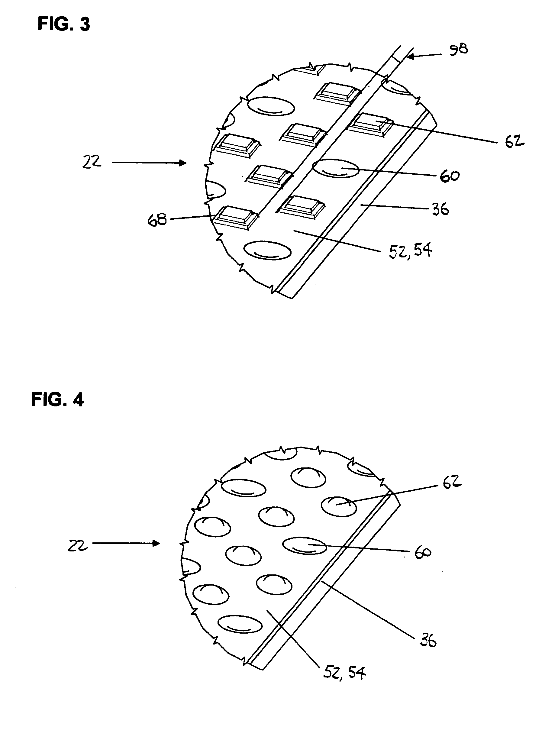
[0033]FIG. 1 illustrates a housingless plate heat exchanger 20 incorporating the present invention as may be used, for example, for cooling and / or temperature control of transmission oil by means of the engine coolant in a vehicle.

[0034] The heat exchanger 20 includes stacked heat exchanger plates 22, 24 having four openings 26-29 that form four channels 30-33 in the plate heat exchanger, which serve to supply or discharge oil and coolant.

[0035] The elements of the plate heat exchanger may advantageously be made from aluminum sheet having an expedient solder coating, and the heat exchanger plates 22, 24 may be advantageously produced from aluminum sheet with a sheet thickness of about 0.3 mm by means of suitable sheet deformation methods.

[0036] The heat exchanger plates 22, 24 are designed trough-like with a continuous raised edge 36 therearound, with the stacked plates 22, 24 sealed around the raised edges 36 and the plate heat exchanger 20 sealed on the top by a cover plate 38 ...


PUM


Abstract

A plate heat exchanger including first and second sets of heat exchanger plates. The second set plates are alternately stacked with the first set plates to form flow channels therebetween. The first set plates have first projections protruding in one direction from the plane of the plates and second projections protruding in the opposite direction from the plane of the plate. The second set plates have third projections protruding in the one direction from the plane of the second set plates. The first projections are connected to adjacent second set plates and the second projections protrude into the space between at least two of the third projections. The second projections may be spaced from and not connected to the second set plates, with the height of the third projections from the second set plates being greater than the height of the first and second projections from opposite sides of the first set plates.

Description

CROSS REFERENCE TO RELATED APPLICATION(S) [0001] Not applicable. STATEMENT REGARDING FEDERALLY SPONSORED RESEARCH OR DEVELOPMENT [0002] Not applicable. REFERENCE TO A MICROFICHE APPENDIX [0003] Not applicable. TECHNICAL FIELD [0004] The present invention relates to a plate heat exchanger, and more particularly a plate heat exchanger having at least two types of heat exchanger plates stacked to form flow channels between them with projections protruding from the plane of the plate connected to the adjacent heat exchanger plate. BACKGROUND OF THE INVENTION AND TECHNICAL PROBLEMS POSED BY THE PRIOR ART [0005] Plate heat exchangers having projections from the plates are known, for example, from FIG. 8 of EP 742 418 B1 (prescribed there as oil coolers). They are also known from numerous other publications for other types of applications, including DE 100 34 343C2, DE 201 19 565 U1 and U.S. Pat. No. 4,781,248. [0006] Internal inserts, as opposed to projections formed in the plates themsel...

Claims


Application Information

Patent Timeline
Patent Type & Authority Applications(United States)
IPC IPC(8): F28F3/08
CPCF28D9/005F28F3/044F28D2021/0089
Inventor BROST, VIKTOR
Owner MODINE MFG CO
Why Eureka
Try Eureka