Illumination system for material inspection

a material inspection and illumination system technology, applied in the field of illumination systems, can solve the problems of unsuitable products for sale, unusable web materials, and unusable products, and achieve the effects of reducing brightness, reducing brightness, and increasing ligh

Active Publication Date: 2007-01-11
WINTRISS ENG
View PDF14 Cites 38 Cited by
  • Summary
  • Abstract
  • Description
  • Claims
  • Application Information

AI Technical Summary

Benefits of technology

[0015] In one example of the web inspection system, the arrangement is such that a pattern of light is focused toward each pixel. Thus, any defect will have the effect of producing a darker region in the resulting image, since the brightness level will be reduced in each affected pixel. In another embodiment, a dark pattern is focused toward each pixel by placing a diffuser with an opaque spot centered on the light source between the light source and pixels, and placing the lens between the diffuser and line scan camera so as to focus the dark spot on each pixel. With this arrangement, defects such as bumps and depressions will increase the amount of light “seen” by the affected pixel and will show up as bright spots in a darker overall image.
[0016] The web inspection system may therefore be able to see flaws which extend in any direction relative to the machine or material travel direction, and will provide better control of sensitivity of the image. The system requires only one point light source and one or two lenses per line scan camera, and thus will be relatively efficient to construct, install, use, and maintain. These and other features of the present invention will become apparent from a reading of the following description, and may be realized by means of the instrumentalities and combinations particularly pointed out in the appended claims.

Problems solved by technology

Manufacturing systems often require surface inspection to detect flaws and contamination that render a product unsuitable for sale.
Failure to detect these flaws and defects may result in thousands of feet of unusable web material.
However, this basic illumination may not reveal the presence of certain types of defects on the surface or optical transmission defects.
For example, the images may highlight dust or other non-defect artifacts on the inspected surface, resulting in false identification of defects.
These “in-line” or “machine-direction” defects are relatively common, but when illuminated, cause light to be reflected or refracted only in the plane of the camera sensors.
Since light is being scatter from adjacent areas on the web, the camera sensors may not register a perceptible or meaningful change in brightness.
In this way, the camera may not detect the presence of the machine-direction defect.
Defects which cannot be seen with uniform illumination become visible when utilizing these types of illumination schemes.
The above-described illumination systems present disadvantages of use in a surface inspection system.
Because such illumination may highlight dust on the surface, this type of illumination may not be suitable for harsh environments.
Since these systems often miss “in-line” defects, such as scratches, these systems fail to detect common and serious defects.
The use of multiple light sources increases the cost of a defect detection system as well as the cost for operation of the system.
Strobe or switched lights require switching and control hardware which increases cost and complexity of the system.
In addition, the existing illumination systems limit the resolution of the defect detection.
In this way, the amount of light information received at one sensor changes when a defect is in that sensor's associated small portion, exposing the defect in that small portion.
With this arrangement, defects such as bumps and depressions will increase the amount of light “seen” by the affected pixel and will show up as bright spots in a darker overall image.

Method used


Image

  • Illumination system for material inspection
  • Illumination system for material inspection
  • Illumination system for material inspection

Examples


Embodiment Construction

[0040] Detailed descriptions of examples of the invention are provided herein. It is to be understood, however, that the present invention may be exemplified in various forms. Therefore, the specific details disclosed herein are not to be interpreted as limiting, but rather as a representative basis for teaching one skilled in the art how to employ the present invention in virtually any detailed system, structure, or manner.

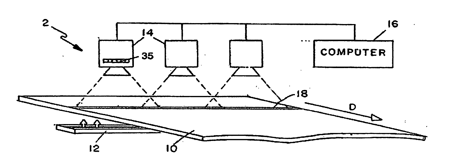
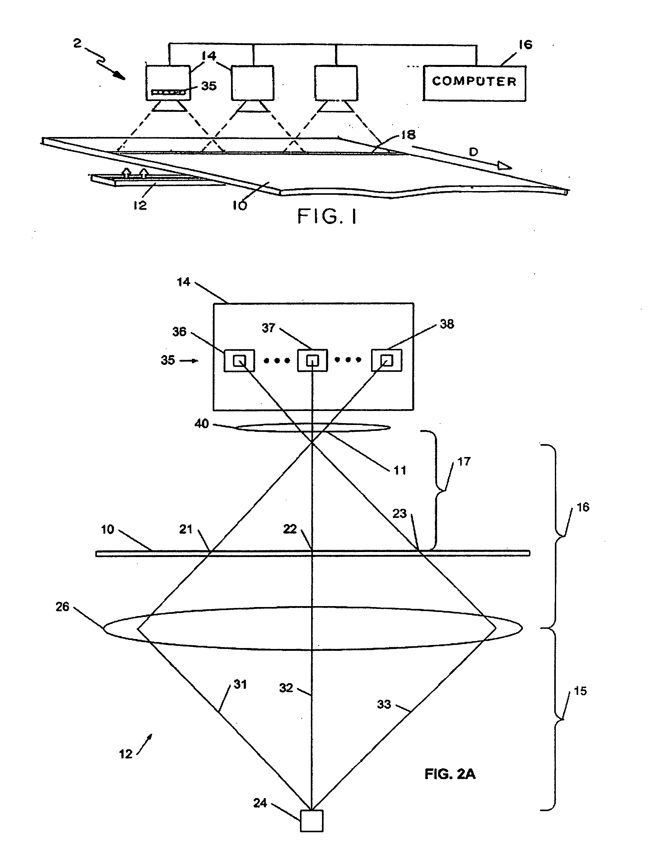
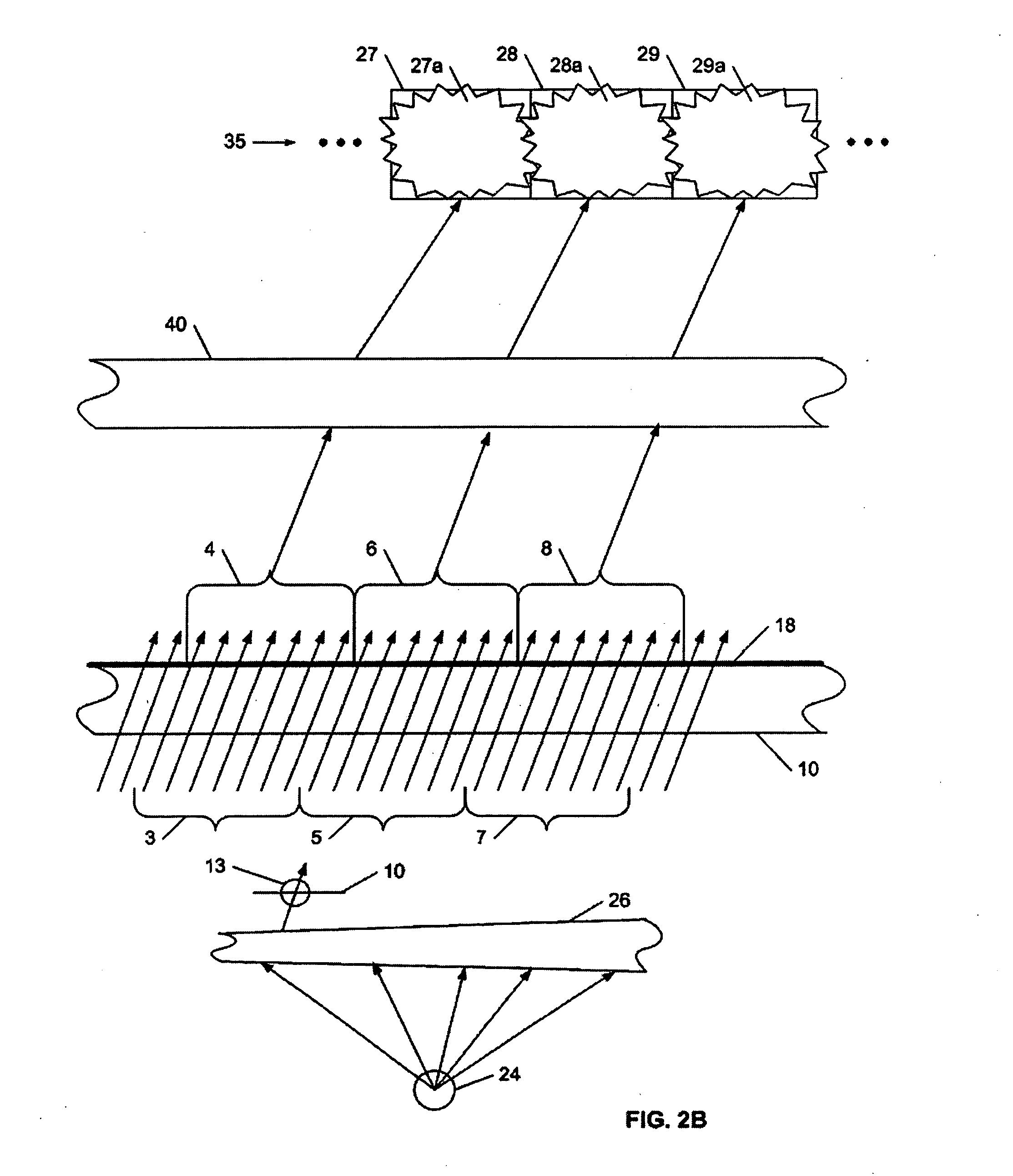
[0041]FIG. 1 illustrates a web inspection system 2 including a web material 10 moving in a machine direction D, and an illumination system 12 according to an exemplary embodiment of the invention for illuminating the web 10. Each fixed line scan camera 14 has a row of pixels 35 directed on a portion of the width of the web 10. Each camera will be associated with a respective light source and lens in the exemplary embodiment, such that the housing of the illumination system 12 as illustrated in FIG. 1 will contain a series of three light sources and a cylindrical...


PUM

PropertyMeasurementUnit
focal lengthaaaaaaaaaa
lengthaaaaaaaaaa
focal lengthaaaaaaaaaa

Abstract

An illumination system for a web inspection process is provided. The illumination system cooperates with a camera system to detect defects in the web material, with the camera having a line of light sensors. The illumination system has a single light source and a lens that arranges the light into a set of light beams. Each beam is projected to an associated small portion of the web, so that together, the light beams illuminate an inspection line on the web. After the beams have been projected onto the web, light from each individual web portion is received by one sensor in the camera. Depending on the camera and light configuration, the light may be either refracted through or reflected from the web. If a defect is present in one small portion, then some of the light beam associated with that portion will follow a different path than when no defect is present, and will not be received at the sensor. In this way, the amount of light information received at one sensor changes when a defect is in that sensor's associated small portion, exposing the defect in that small portion.

Description

CROSS REFERENCE TO RELATED APPLICATIONS [0001] This application claims the benefit of priority of U.S. provisional application Ser. No. 60 / 538,377 filed Jan. 22, 2004, which is incorporated herein by reference in its entirety.STATEMENT REGARDING FEDERALLY SPONSORED RESEARCH AND DEVELOPMENT [0002] Not applicable. REFERENCE TO A COMPUTER LISTING, A TABLE, OR A COMPUTER PROGRAM LISTING COMPACT DISK APPENDIX [0003] Not applicable. BACKGROUND [0004] 1. Field [0005] The preset invention relates generally to material inspection, and more specifically to an illumination system to facilitate detection of defects on a web surface. [0006] 2. Description of Related Art [0007] Manufacturing systems often require surface inspection to detect flaws and contamination that render a product unsuitable for sale. For example, surface inspection systems are utilized to inspect moving webs of materials. A “web” is a flat material produced continuously in large quantities and at very high rates. Typical w...

Claims


Application Information

Patent Timeline
Patent Type & Authority Applications(United States)
IPC IPC(8): G01N21/84G01N21/89G01N21/896
CPCG01N21/8903G06T2207/30124G06T7/0004G01N21/896
Inventor KIRALY, CHRISTOPHER M.
Owner WINTRISS ENG
Why Eureka
Try Eureka