Constrained image deblurring for imaging devices with motion sensing

a motion sensing and imaging device technology, applied in the field of imaging processing, can solve the problems of blurred image, increased risk of blurring, and difficulty in stabilizing the camera

Inactive Publication Date: 2007-01-11
SEIKO EPSON CORP
View PDF9 Cites 62 Cited by
  • Summary
  • Abstract
  • Description
  • Claims
  • Application Information

AI Technical Summary

Problems solved by technology

Despite a person's best efforts, slight involuntary movements while taking a picture may result in a blurred image.
The camera's size may make it difficult to stabilize the camera.
Pressing the camera's shutter button may also cause jitter.
As the amount of exposure time increases, the risk of blurring also increases because the camera must remain stationary for a longer period of time.
Some expensive devices attempt to compensate for camera motion problems by incorporating complex adaptive optics into the camera that respond to signals from sensors.
Although these various remedies are helpful in reducing or eliminating blurring, they have limits.
It is not always feasible or practical to use a tripod or stand.
And, in some situations, such as taking a picture from a moving platform like a ferry, car, or train, using a tripod or stand may not sufficiently ameliorate the problem.
The complex and expensive components needed for adaptive optics solutions are too costly for use in all digital cameras, particularly low-end cameras.
Although successful to some degree, these algorithms are also deficient.

Method used

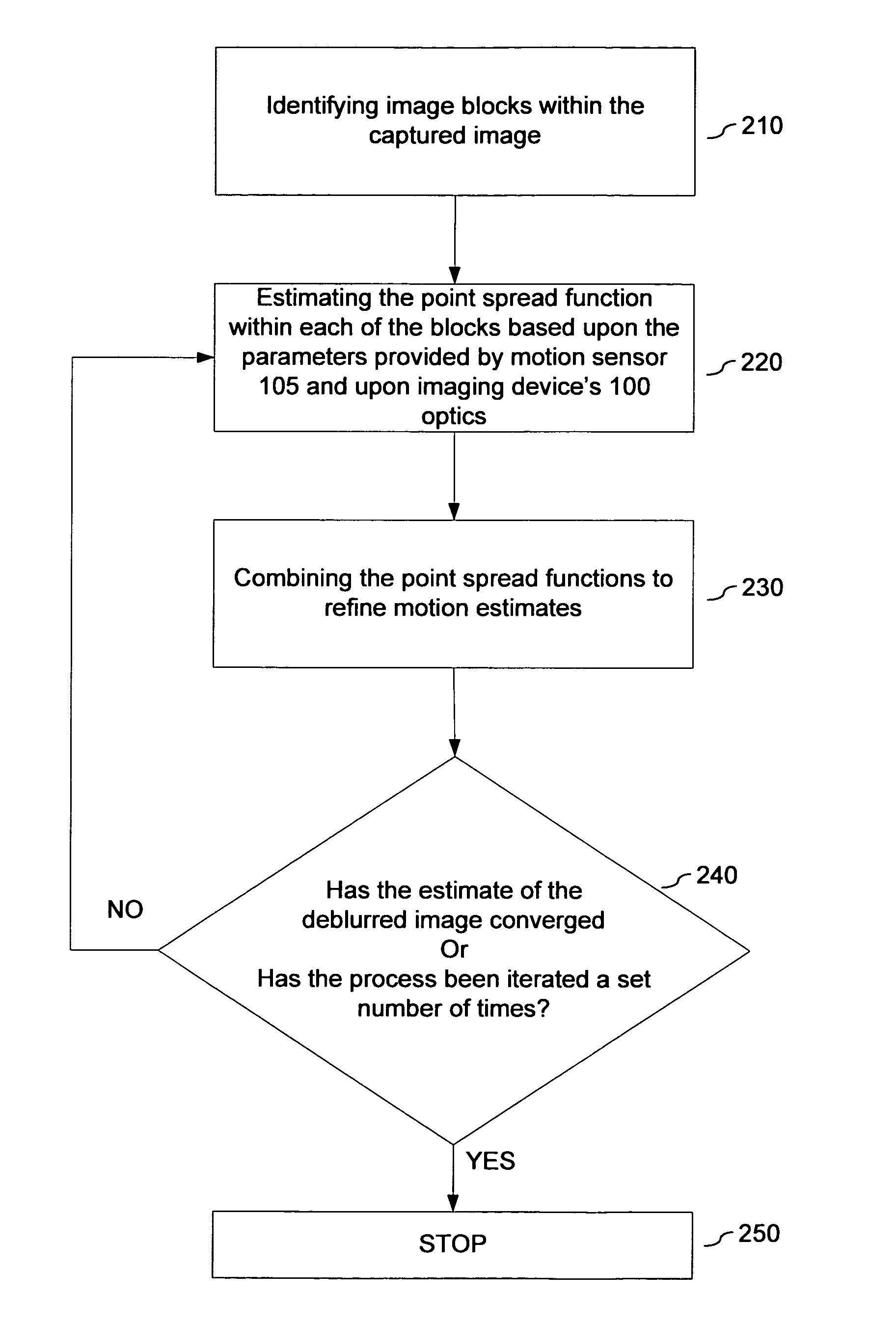
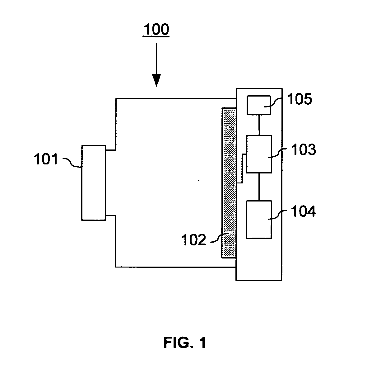
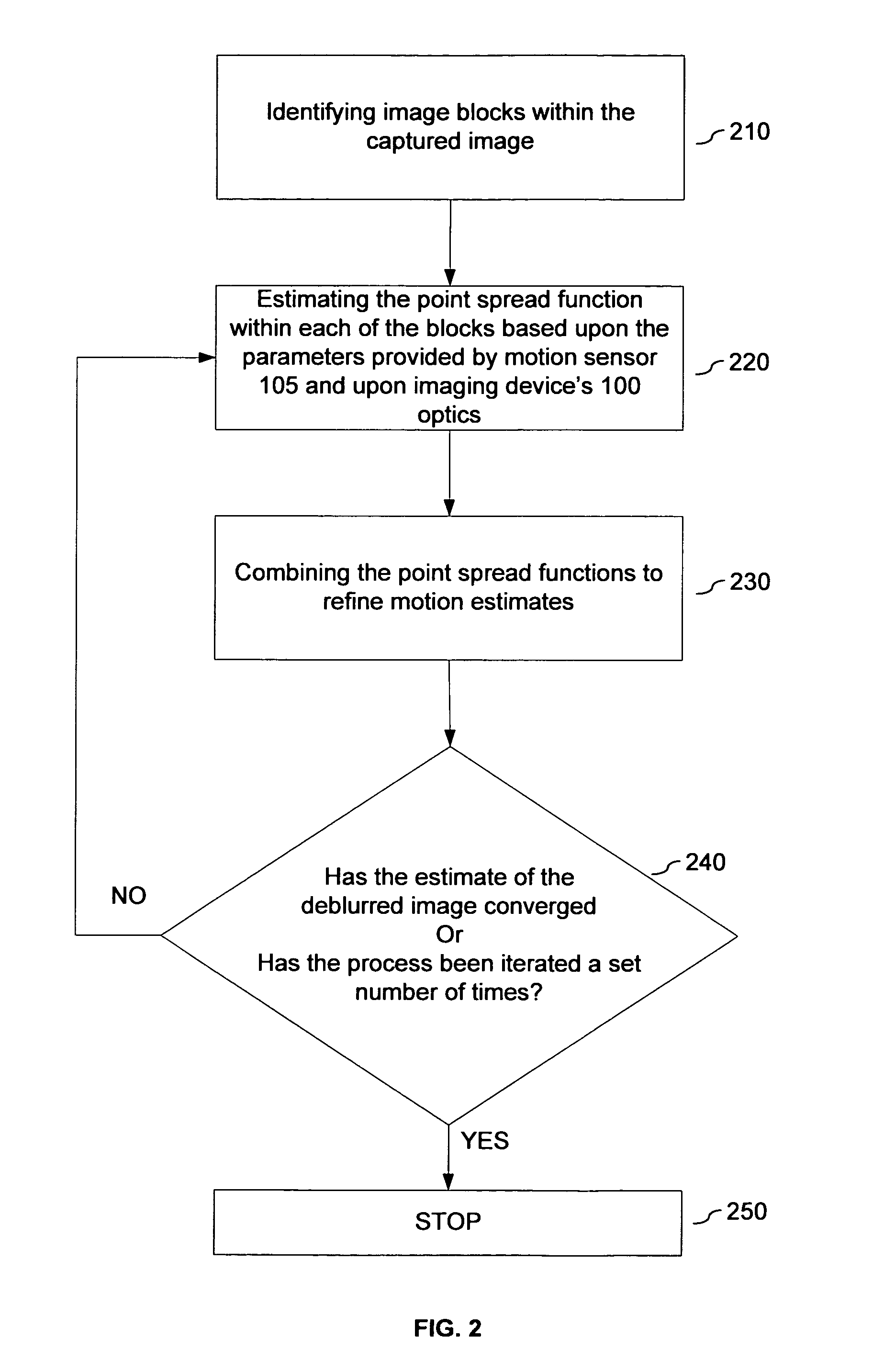

Image

  • Constrained image deblurring for imaging devices with motion sensing
  • Constrained image deblurring for imaging devices with motion sensing
  • Constrained image deblurring for imaging devices with motion sensing

Examples


Embodiment Construction

[0025] In the following description, for purposes of explanation, specific details are set forth in order to provide an understanding of the invention. It will be apparent, however, to one skilled in the art that the invention can be practiced without these details. One skilled in the art will recognize that embodiments of the present invention, described below, may be performed in a variety of ways and using a variety of means. Those skilled in the art will also recognize additional modifications, applications, and embodiments are within the scope thereof, as are additional fields in which the invention may provide utility. Accordingly, the embodiments described below are illustrative of specific embodiments of the invention and are meant to avoid obscuring the invention.

[0026] Reference in the specification to “one embodiment” or “an embodiment” means that a particular feature, structure, characteristic, or function described in connection with the embodiment is included in at le...


PUM


Abstract

Systems and methods are disclosed for deblurring a captured image using parametric deconvolution, instead of a blind, non-parametric deconvolution, by incorporating physical constraints derived from sensor inputs, such as a motion sensor, into the deconvolution process to constrain modifications to the point spread function. In an embodiment, a captured image is deblurred using a point spread function obtained from the cross-validation of information across a plurality of image blocks taken from the capture image, which image blocks are deconvolved using parametric deconvolution to constrain modifications to the point spread function.

Description

BACKGROUND [0001] 1. Field of the Invention [0002] The present invention relates generally to the field of imaging processing, and more particularly to systems and methods for correcting blurring introduced into a captured image by motion of the imaging device while capturing the image. [0003] 2. Background of the Invention [0004] A digital camera captures an image by integrating the energy focused on a semiconductor device over a period of time, referred to as the exposure time. If the camera is moved during the exposure time, the captured image may be blurred. Several factors can contribute to camera motion. Despite a person's best efforts, slight involuntary movements while taking a picture may result in a blurred image. The camera's size may make it difficult to stabilize the camera. Pressing the camera's shutter button may also cause jitter. [0005] Blurring is also prevalent when taking pictures with long exposure times. For example, photographing in low light environments typi...

Claims


Application Information

Patent Timeline
Patent Type & Authority Applications(United States)
IPC IPC(8): G06K9/40
CPCH04N5/23248H04N5/23254H04N5/2327G06T2207/20201G06T5/10G06T2207/20056G06T5/003H04N23/6811H04N23/68H04N23/684
Inventor BHATTACHARJYA, ANOOP K.
Owner SEIKO EPSON CORP
Why Eureka
Try Eureka