Blur correction camera system

a camera system and blue light technology, applied in the field of blue light correction camera system, can solve the problems of inability to inability to fully recover the raw image, and inability to detect errors, etc., to achieve a large amount of information, reduce the information volume, and reduce the information volume

Inactive Publication Date: 2006-05-25
NIKON CORP
View PDF18 Cites 57 Cited by
  • Summary
  • Abstract
  • Description
  • Claims
  • Application Information

AI Technical Summary

Benefits of technology

[0047] (3) A blur correction camera according to the present invention includes a vibration detection unit that detects a vibration and outputs a vibration detection signal, a reference value computing unit that computes a reference value for the vibration detection signal a blur correction optical system that is driven based upon the reference value and the vibration detection signal and corrects an image blur, an image-capturing unit that captures an image formed by a photographic optical system that includes the blur correction optical system, a point spread function computing unit that computes a point spread function needed in an image restoration com

Problems solved by technology

This, in turn, means that the complete recovery of the raw image is not possible.
However, the following problems exist in the optical blur correction and the image restoration in the related art described above.
However, this reference value is known to be readily affected by drift attributable to temperature changes.
For this reason, a detection error is bound to manifest in the detected vibration extent, which gives rise to a problem in that blurring is not completely eliminated from the image having undergone the optical blur correction.
In addition, an optical blur correction apparatus often includes a switch operated to switch on/off a blur correction operation, and if the user fails to turn on the switch and a blur correction is not executed during the photographing operation, a blurred image will result.
This gives rise to a problem in that the image quality is lowered by an unnecessary stripe pattern that is bound to manifest in the image.
While this stripe pattern does not pose a very serious problem as long as the initial blurring is insignificant, it manifests prominently if the extent of blurring is significant and in such a case, the stripe pattern becomes problematic.
In addition, cameras havin

Method used


Image

  • Blur correction camera system
  • Blur correction camera system
  • Blur correction camera system

Examples


first embodiment

[0096] (First Embodiment)

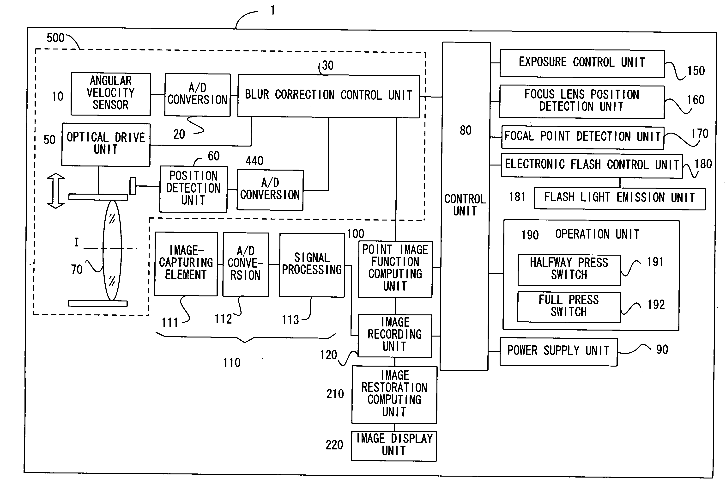
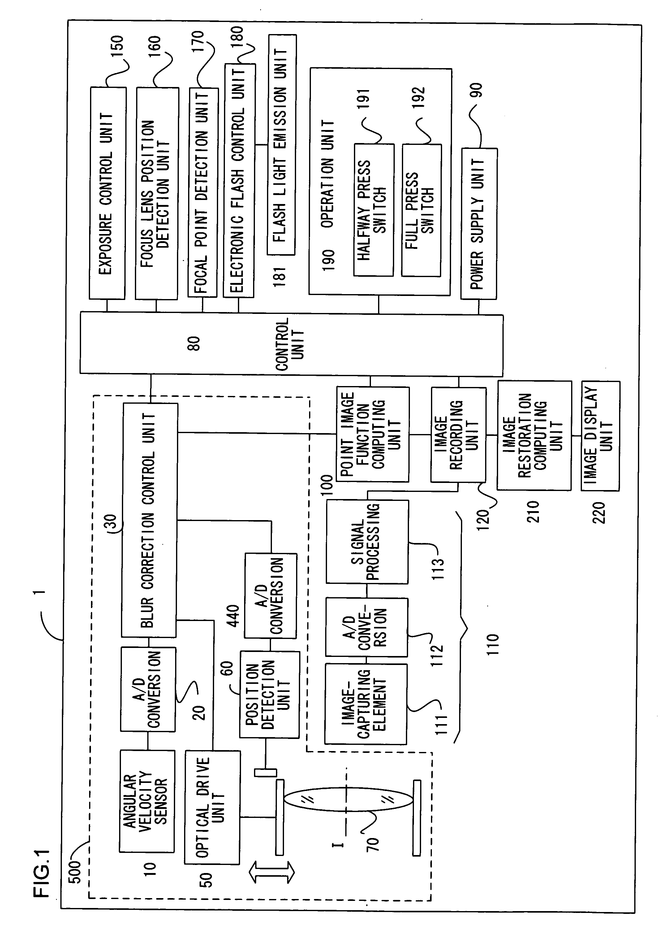
[0097]FIG. 1 is a block diagram showing a system configuration adopted in a first embodiment of a blur correction camera according to the present invention.

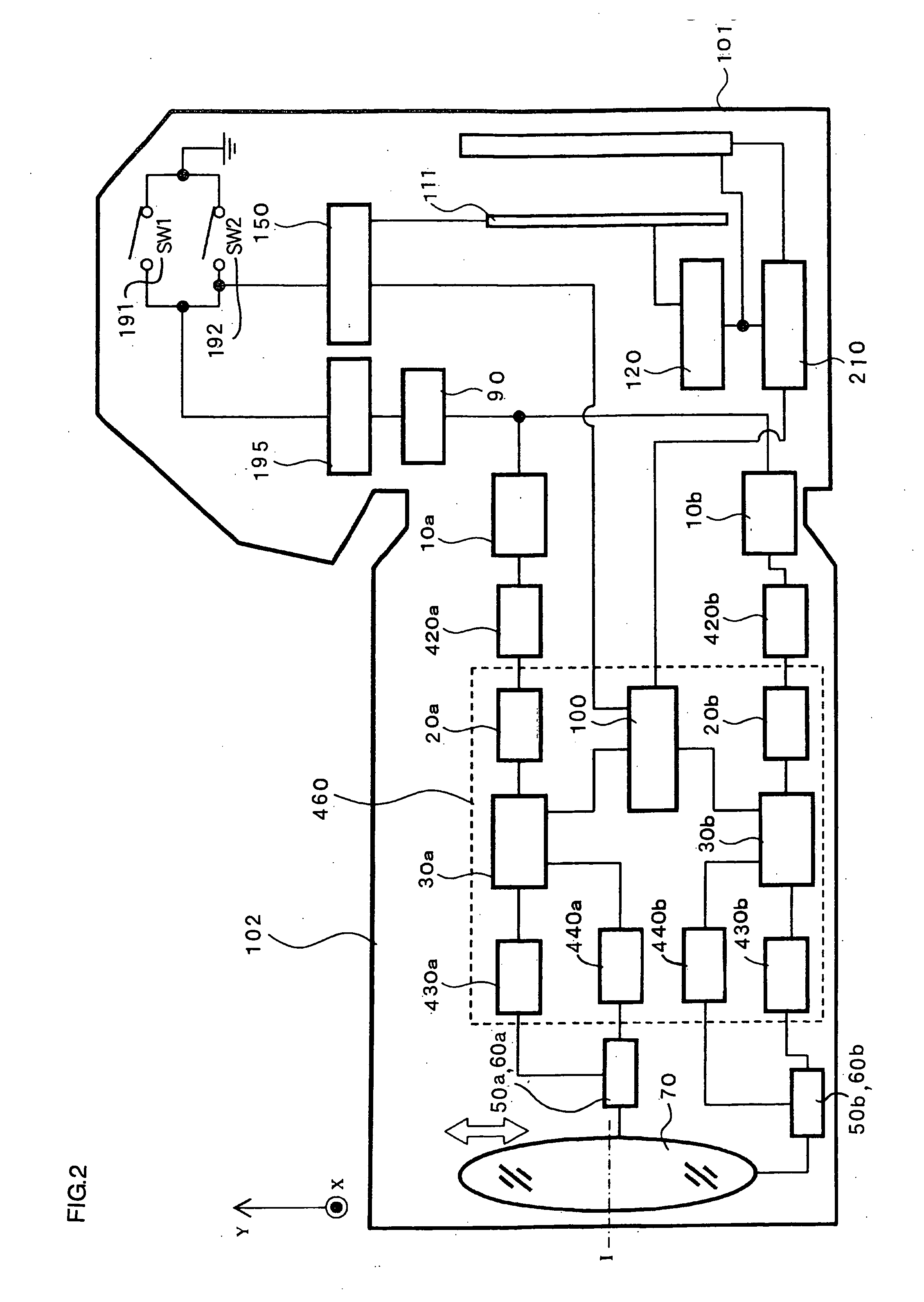
[0098] The blur correction camera 1 achieved in the embodiment constitutes a camera system having an optical blur correction function and is capable of image restoration. FIG. 2 is a diagram of a block configuration that may be adopted in the blur correction camera 1 realized as a single lens reflex camera that allows the use of interchangeable lens barrels. As shown in FIG. 2, the camera system includes a camera body 101 and a lens barrel 102.

[0099] The blur correction camera 1 is a digital still camera that electronically captures an image and includes an optical correction system (or a blur correction optical system) 500.

[0100] Angular velocity sensors 10 in the optical system 500 constitute a vibration detection unit that detects a vibration to which the blur correction camera 1 is subjected, as an...

second embodiment

[0163] (Second Embodiment)

[0164] In this embodiment, the system configuration of the first embodiment is modified by adding a blur correcting operation selector switch 194 and a signal flow control unit 452.

[0165]FIG. 9 is a block diagram showing the system configuration adopted in the embodiment, and FIG. 10 is a diagram showing the block configuration adopted in the system. The same reference numerals are assigned to components having functions similar to those in the first embodiment to minimize the need for a reputed explanation thereof.

[0166]FIG. 11 is a block diagram illustrating the operation executed at the blur correction control unit. FIG. 11 shows the signal flow control unit 452 installed to switch on / off a blur correcting operation when the output from the reference value computing unit 31 is provided to the point-image function computing unit 100.

[0167] The blur correcting operation selector switch (VRSW) 194 is operated to switch on / off an optical blur correcting o...

third embodiment

[0202] (Third Embodiment)

[0203] A third embodiment includes an image restoring device and a camera body provided independently of each other. The same reference numerals are assigned to components having similar functions to those in the first embodiment to minimize the need for a repeated explanation thereof.

[0204] The following is a detailed explanation of the embodiment of the present invention, given in reference to drawings and the like. FIG. 14 is a block diagram of the system configuration adopted in the third embodiment of the blur correction camera according to the present invention.

[0205] The blur correction camera body 1 in the embodiment adopts a structure achieved by adding a function correcting unit 105, an interface unit 130 and an image restoration decision-making unit 140 in the structure in the first embodiment, with an image restoration computing unit 210 constituting part of an image reproduction device 2, which is a separate device independent of the camera bo...


PUM


Abstract

A blur correction camera system includes a blur correction lens driven based upon the vibration detection signal detected by an angular velocity sensor, that corrects an image blur, a point-image function computing unit that computes a point spread function, and an image restoration computing unit that corrects an image blur by executing image restoration through image processing on a captured image by using the point spread function. The image blur that cannot be completely corrected by the blur correction lens is further corrected through image restoration so as to obtain a high quality image.

Description

INCORPORATION BY REFERENCE [0001] The disclosures of the following priority applications are herein incorporated by reference: [0002] Japanese Patent Application No. 2002-374644 filed Dec. 25, 2002 [0003] Japanese Patent Application No. 2002-374661 filed Dec. 25, 2002 [0004] Japanese Patent Application No. 2002-374687 filed Dec. 25, 2002 [0005] Japanese Patent Application No. 2002-374704 filed Dec. 25, 2002 [0006] Japanese Patent Application No. 2002-374724 filed Dec. 25, 2002 [0007] Japanese Patent Application No. 2002-374748 filed Dec. 25, 2002 [0008] Japanese Patent Application No. 2002-374739 filed Dec. 25, 2002 [0009] Japanese Patent Application No. 2003-026098 filed Feb. 3, 2003 TECHNICAL FIELD [0010] The present invention relates to a technology adopted in a camera or the like to correct an image blur by detecting a vibration caused by an unsteady hand movement or the like. BACKGROUND ART [0011] There are cameras known in the related art, that have a blur correcting function ...

Claims


Application Information

Patent Timeline
IPC IPC(8): G03B17/00H04N5/232
CPCG03B2205/0007G03B2217/005H04N5/23212H04N5/23248H04N5/23258H04N5/23264H04N5/23287H04N23/67H04N23/682H04N23/68H04N23/6812H04N23/687
Inventor TOMITA, HIROYUKIUSUI, KAZUTOSHIKITANO, KENICHIONO, YOSHIKO
Owner NIKON CORP
Why Eureka
Try Eureka