Fastener for floor mat

a technology for floor mats and clamping parts, applied in the field of fasteners, can solve the problems of troublesome inserting the tip end portion of the lower clamping member into the slit of the carp

Active Publication Date: 2007-01-18
PIOLAX CO LTD
View PDF10 Cites 29 Cited by
  • Summary
  • Abstract
  • Description
  • Claims
  • Application Information

AI Technical Summary

Benefits of technology

[0019] A height of the upper surface of the guide protrusion, may also be lower than a height of the receiving portion. In this state, since the upper surface of the guide protrusion is lower than the receiving wall 10 in height, the peripheral portion of the installation hole is disposed on the upper surface of the guide protrusion, thereby preventing the peripheral portion of the installation hole from being disposed on the engaging portion. This results in an easy insertion operation.
[0020] The fastener may also comprise a shoulder wall formed on an inner surface of the upper clamping member, a first stopper wall formed between a tip end portion of the lower clamping member and the receiving portion, the first stopper wall coming into contact with the shoulder wall to thereby prevent displacement of the upper clamping member in one direction, and a second stopper wall formed at the receiving portion, the second stopper wall coming into contact with the locking portion to thereby prevent displacement of the upper clamping member in another direction. In this case, for example, the horizontal displacements of the upper clamping member with respect to the lower clamping member can be prevented.

Problems solved by technology

However, inserting the tip end portion of the lower clamping member into the slit of the carpet is troublesome, since it is required to be forcibly inserted into the slit so as to be located at the backside of the carpet.

Method used


Image

  • Fastener for floor mat
  • Fastener for floor mat
  • Fastener for floor mat

Examples


Embodiment Construction

[0053] In the following paragraphs, some preferred embodiments of the present invention will be described by way of example and not limitation. It should be understood based on this disclosure that various other modifications can be made by those in the art based on these illustrated embodiments.

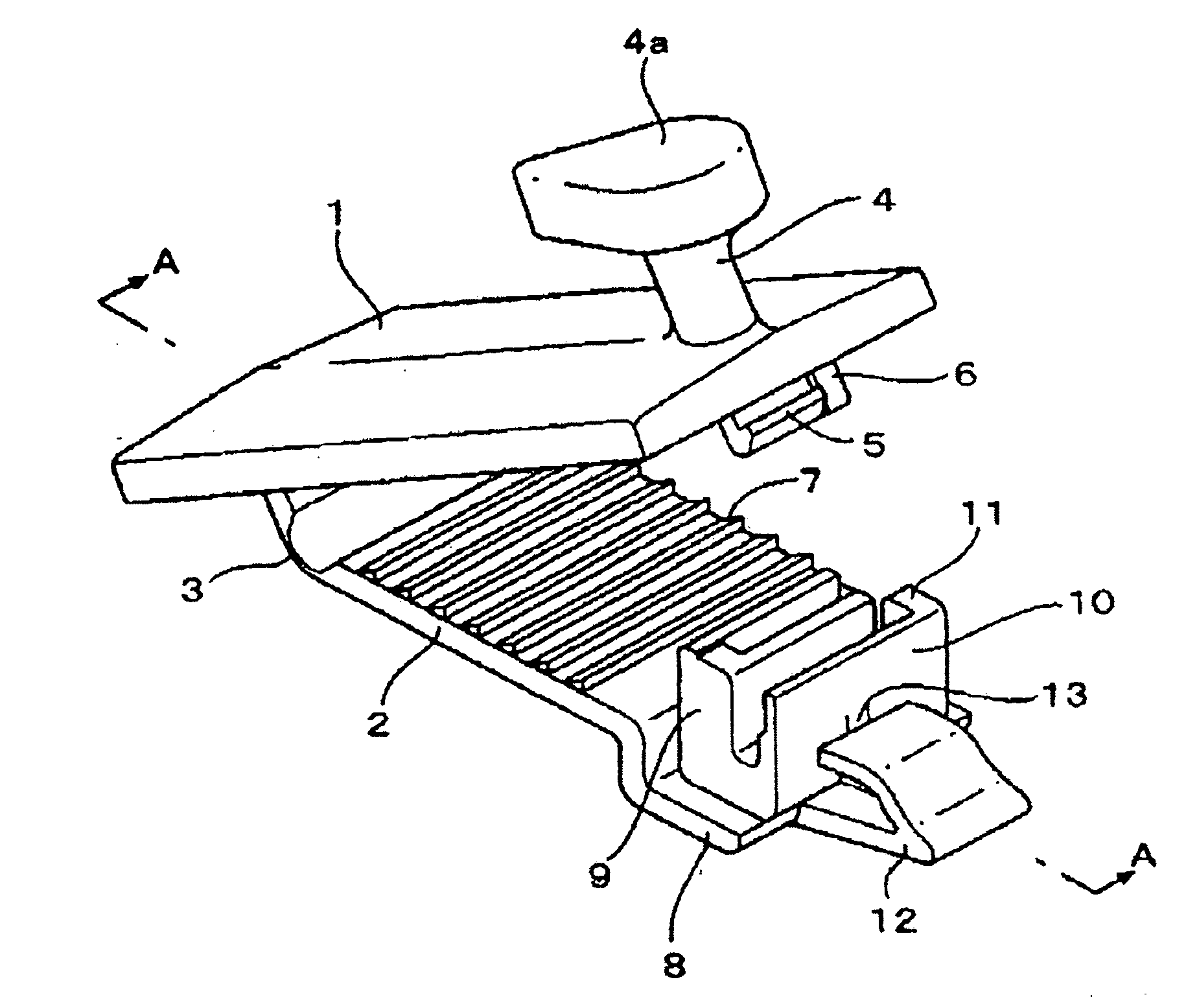
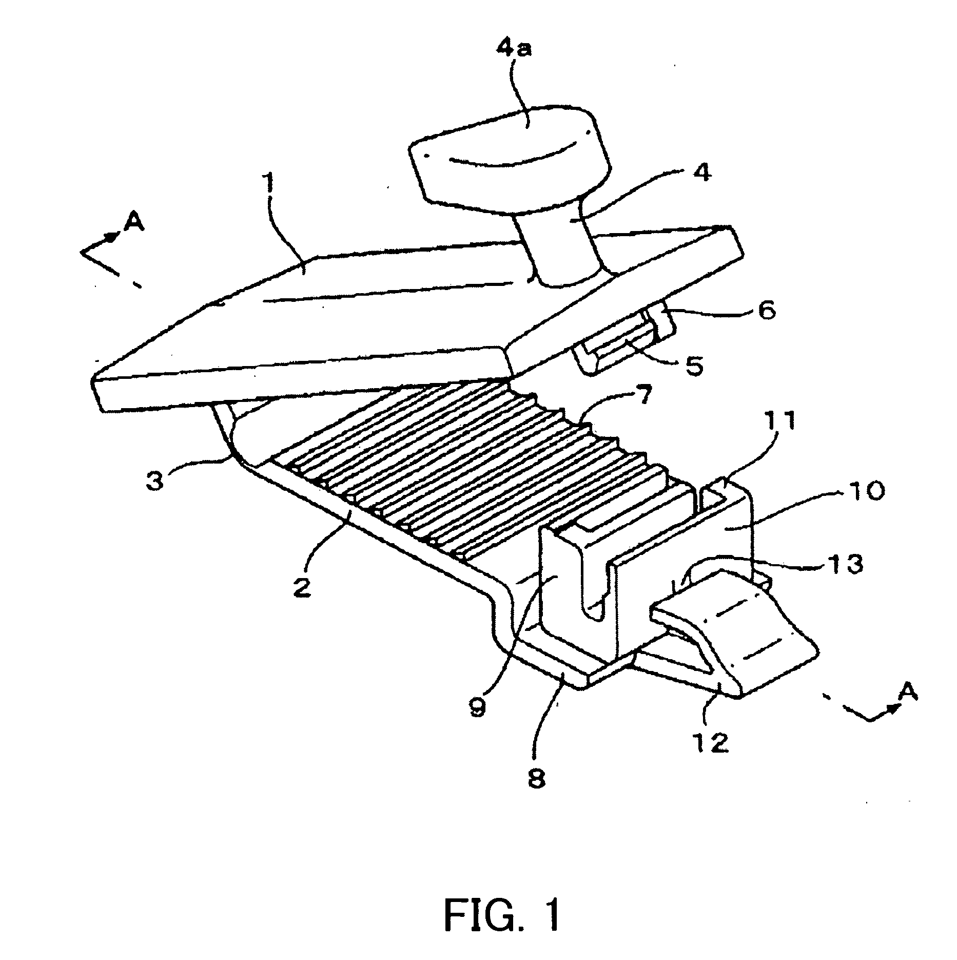
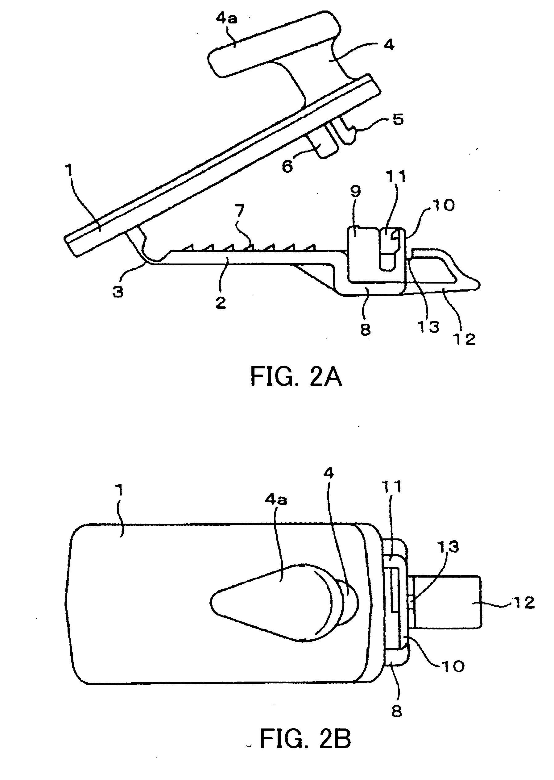
[0054] A fastener according to an embodiment of the present invention is shown in FIGS. 1-3. The faster is used to secure a floor mat to a carpet laid on a surface of a floor, such as, e.g., an automobile floor. Like a conventional faster of this kind, this fastener is, for example an integrally molded article made of synthetic resin equipped with an upper clamping member 1 and a lower clamping member 2 resiliently connected via a thin hinge portion 3.

[0055] The upper clamping member 1 includes, for example, an engaging projection 4 upwardly protruded from an upper surface of one end portion of the upper clamping member 1. This engaging projection 4 is configured to be inserted in and enga...


PUM


Abstract

A fastener for securing an automobile floor mat to a carpet laid on a floor within an automobile includes a lower clamping member, an upper clamping member, a hinge portion connecting the upper clamping member and the lower clamping member in a pivotable manner, a supporting portion forwardly protruded from a tip end portion of the lower clamping member, and a guide protrusion forwardly protruded from a tip end portion of the supporting portion and configured to so as to facilitate an insertion of the supporting portion and the lower clamping member to a backside of the carpet via a slit formed in the carpet. The upper clamping member has an engaging projection formed at an outer surface of a tip end portion thereof and configured to be inserted in an attaching hole formed in the floor mat and a locking portion formed at an inner surface of the tip end portion. The supporting portion has an engaging portion for engaging the engaging portion of the upper clamping member. An upper surface of the guide protrusion is tapered.

Description

[0001] This application claims priority under 35 U.S.C. §119 to Japanese Patent Application No. 2005-206970 filed on Jul. 15, 2005, the entire disclosure of which is incorporated herein by reference in its entirety. TECHNICAL FIELD [0002] The present invention relates to a fastener for securing a floor mat to a carpet laid on a surface of a floor, e.g., an automobile floor. BACKGROUND OF THE INVENTION [0003] The following description sets forth the inventor's knowledge of related art and problems therein and should not be construed as an admission of knowledge in the prior art. [0004] A conventional fastener of this kind is an integrally molded article made of synthetic resin having an upper clamping member and a lower clamping member resiliently connected via a thin hinge portion in a pivotable manner. The lower clamping member is provided with an engaging projection upwardly protruded from the tip end portion thereof, and the upper clamping member is provided with a slit for recei...

Claims


Application Information

Patent Timeline
Patent Type & Authority Applications(United States)
IPC IPC(8): A47G27/04
CPCY10T16/10B60N3/046
Inventor AOKI, RYOUKANDA, KAZUNORIOGATA, KOUJI
Owner PIOLAX CO LTD
Why Eureka
Try Eureka