
String instrument

a string instrument and string technology, applied in stringed musical instruments, musical instruments, guitars, etc., can solve the problems of pin and/or string disengagement from the bridge, structurally invasive to the bridge itself, and unreliable bridge pins, etc., and achieve the effect of greater resonan

Inactive Publication Date: 2007-01-18
BABICZ JEFFREY T
View PDF40 Cites 16 Cited by
  • Summary
  • Abstract
  • Description
  • Claims
  • Application Information

AI Technical Summary

Benefits of technology

This configuration maintains soundboard integrity with minimal bracing, enhances acoustic performance by optimizing tensile force, and improves playability and tone quality, reducing the risk of damage and simplifying adjustments.

Problems solved by technology

The disadvantage with bridge pins is that they are structurally invasive to the bridge itself, and over time the bridge can split parallel to the bridge pin holes.
Bridge pins are also unreliable over time because the bridge pinholes have the potential to wear after the player has re-strung the instrument numerous times. The wear on the bridge pinholes compromises the frictional fit of the pin to bridge, allowing the possibility of the pin and / or string to disengage from the bridge.
A major obstacle to maintaining the stability of an acoustic stringed musical instrument over time is caused by the large degree of tensile forces placed on the guitar top in a lateral and semi-vertical manner once the strings are tightened to pitch.
The tensile forces of the strings on the guitar top can cause the structure of the guitar body to deform.
Over time this torque will pull the bridge forward, creating a de-lamination of the bridge-to-soundboard bond and raising the string height drastically.
In many cases the instrument is rendered unplayable due to the damage caused by the tensile forces created by the strings.
Generally, heavy bracing will have a detrimental affect on the acoustic performance of the instrument.
In most cases, substantial bracing will mute the acoustic properties of the instrument.
However, with this type of construction, only a trace amount of tensile force can exist in the soundboard of the instrument.
Consequently, acoustic projection and sustain with this type of instrument is diminished.
Furthermore, a tonal imbalance can be created up and down the neck.
Just as too little tensile energy on the soundboard can have detrimental effects on the instrument's acoustic performance, too much tensile force on the instrument's soundboard will impede the soundboard's ability to move in response to the energy caused by the vibration of the strings.
Consequently, too much tensile forces on the soundboard will dampen the vibrations of the resonance body, decrease the volume of the sound produced by the instrument, and affect the distinctive tonal properties of the instrument.
Consequently, the soundboard does not have enough tensile force to allow for an optimal acoustic performance by the instrument.
The limitations on the soundhole design decreases the fullness of the acoustic tone produced by the instrument and increases the risk of damage to the guitar by placing a large amount of tensile force on the neck which normally has a less secure structure than the body of the guitar.
The disadvantage with this construction is that the soundboard does not have enough tensile force to provide optimal projection, tone and sustain.
Further, the bridge design is complicated and is subject to damage by the tensile forces.
Additionally, a significant amount of the energy created by the strings is absorbed by the bridge body and is not transmitted to the resulting sound produced by the instrument.
Another disadvantage is that the distance between the strings and fingerboard of the instrument, known as the “action,” may be undesirable to the instrument player because the string must be at the same vertical height from the neck to the bridge.
This type of adjustment is inefficient and imprecise and the user must have a significant amount of time and skill in order to make these adjustments properly.

Method used


Image

  • String instrument
  • String instrument
  • String instrument

Examples


Embodiment Construction

[0038] For a more complete understanding of the invention, as well as other objects and further features thereof, reference may be had to the following detailed description of the invention in conjunction with the drawings wherein:

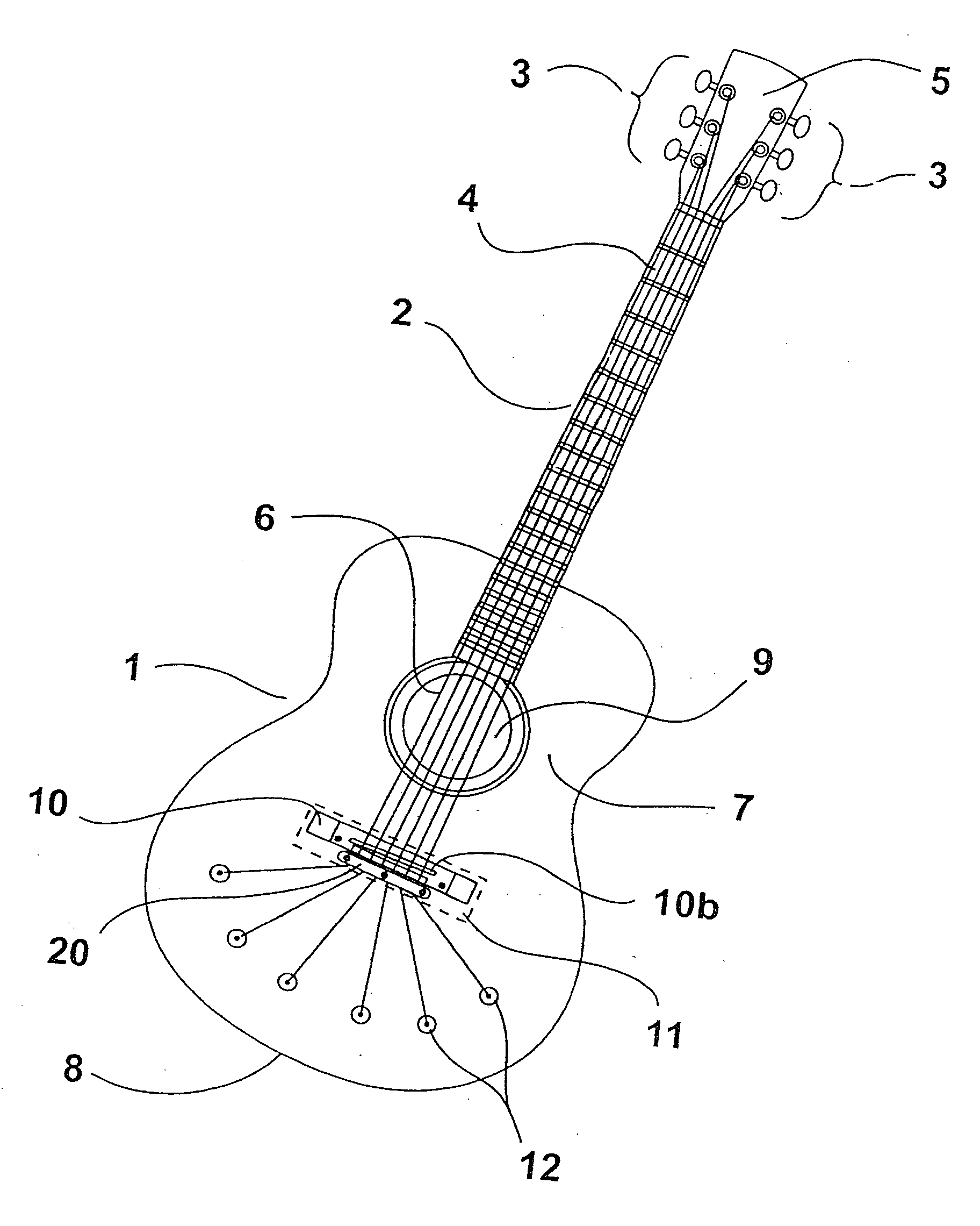
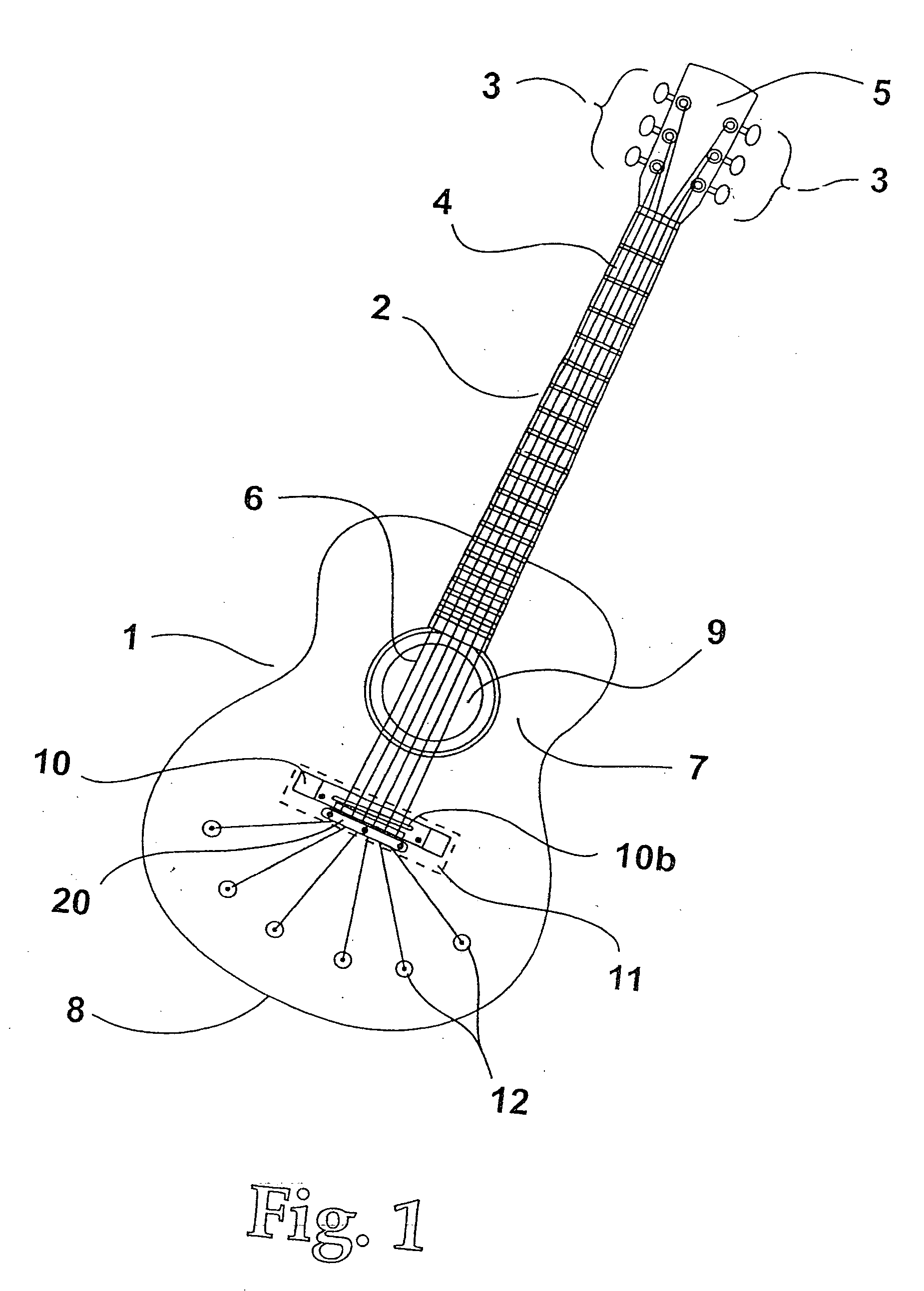
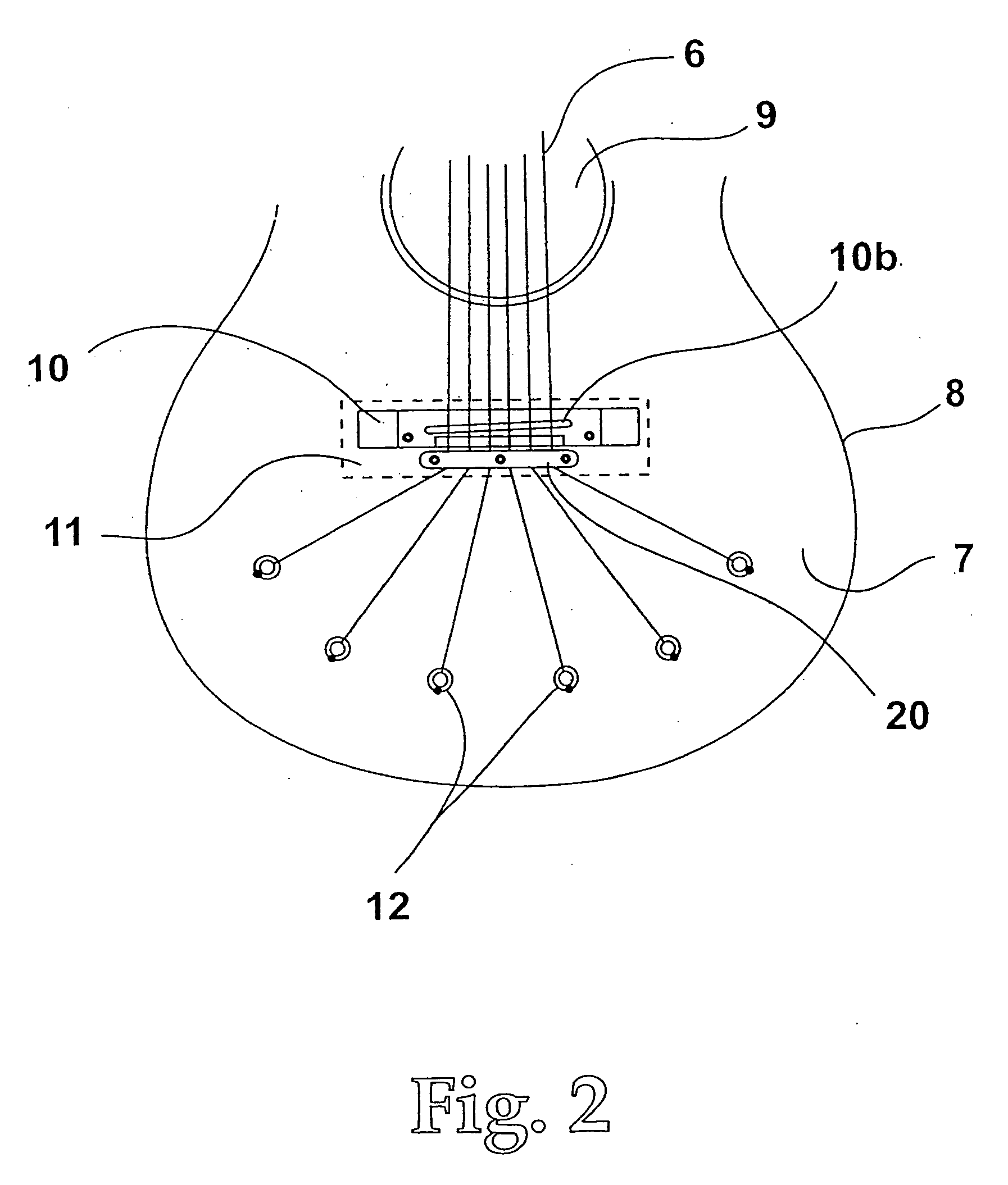
[0039]FIG. 1. shows a hollow body acoustic guitar 1 made preferably of wood, which is connected to a neck 2 assembly. The neck is made of wood or a related material, which is suitable to withstand continual string pull without warping or twisting. The neck has a headstock 5, which holds the tuning pegs 3, which in turn hold the strings 6. The strings are strung at a substantial tension and extend from the fixed point created at the guitar neck to the lower string contacting means. The neck is mated with a fretboard 4 which is made of a hard substance such as rosewood, ebony, or a re-enforced polymer. The material should be strong enough and stable enough to hold metal frets and withstand playing wear. The soundboard 7 which can be made of a known tonewood...


PUM


Abstract

A stringed musical instrument, such as a guitar, whereby the lower end of the strings are anchored to the soundboard itself with one or more of the string anchors being positioned past the bridge. This arrangement provides an offset of the lateral compressive forces to the entire soundboard, therefore allowing the soundboard to vibrate more freely in response to the string vibration, and creating an acoustical perpetuating effect. Due to the inherent strength to this design, internal soundboard bracing can be minimized in weight and size as well, which offers a fuller and louder sound, with an increase in sonic balance and sustain. The string instrument also includes a split bridge design with the bridge body secured on the soundboard and having a saddle thereon for providing a contact point with the strings and a string retainer body secured separately from the bridge body on the soundboard and positioned behind the bridge body having directing means to guide each string.

Description

CROSS REFERENCE TO RELATED APPLICATIONS [0001] The present application is a division and continuation-in-part of my co-pending patent application Ser. No. 10 / 816,478, entitled “String Instrument” filed Apr. 1, 2004, which, in turn, is related to provisional application Ser. No. 60 / 490,991 filed Jul. 30, 2003. All of these applications are incorporated herein by this reference and the benefit of the filing date of these applications is claimed herein as well.BACKGROUND OF THE INVENTION [0002] 1. Field of the Invention [0003] This invention relates to a string instrument and more particularly to an acoustic guitar. [0004] 2. Description of the Related Art [0005] The design of modern acoustical guitars has remained relatively unchanged for many years. A traditional acoustic guitar features a hollow body which has a top, sides and back thus forming a sound chamber. The hollow body is connected to a neck. The guitar has a plurality of strings strung at a substantial tension extending fro...

Claims


Application Information

Patent Timeline
Patent Type & Authority Applications(United States)
IPC IPC(8): G10D3/04G10D3/12
CPCG10D3/12G10D1/085G10D3/04
Inventor BABICZ, JEFFREY T.
Owner BABICZ JEFFREY T
Learn More