Means of detecting faults in alternators

a multi-phase alternator and fault technology, applied in the field of electromechanical devices, can solve problems such as potential electrical hazards

Inactive Publication Date: 2007-01-18
PRATT & WHITNEY CANADA CORP
View PDF7 Cites 9 Cited by
  • Summary
  • Abstract
  • Description
  • Claims
  • Application Information

AI Technical Summary

Benefits of technology

[0006] In one of its aspects, the present invention provides a method...

Problems solved by technology

Unfortunately, if a fault occurs at phases B or C, it will ...

Method used


Image

  • Means of detecting faults in alternators
  • Means of detecting faults in alternators
  • Means of detecting faults in alternators

Examples


Embodiment Construction

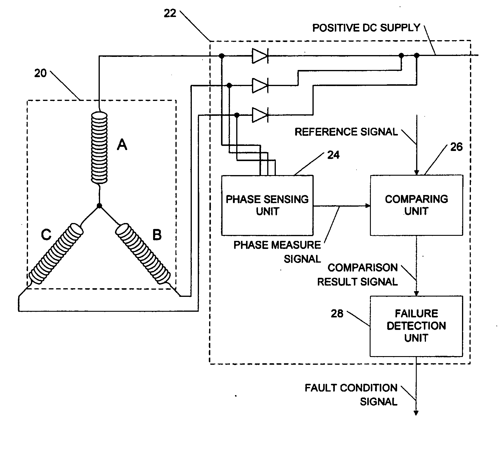
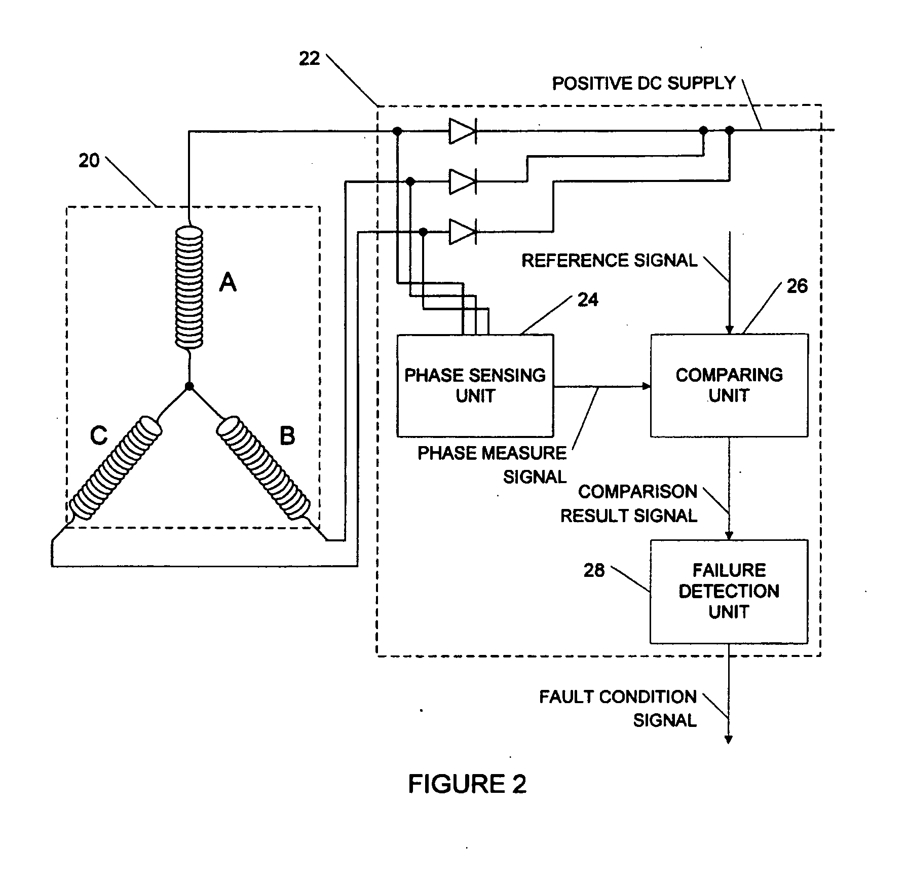
[0017] Now referring to FIG. 2, there is shown an embodiment of an apparatus 22 for detecting one or more faults in a multi-phase alternator 20 comprising 3 phases A, B and C which are star wound.

[0018] The apparatus 22 for detecting one or more faults in a multi-phase alternator 20 comprises a phase sensing unit 24, a comparing unit 26 and a fault detection unit 28. It is to be note that the apparatus 22 may be incorporated in a Electronic Engine Controller (EEC)

[0019] More precisely, the phase sensing unit 24 receives a first voltage signal, a second voltage signal and a third voltage signal provided respectively by phase A, phase B and phase C. Using the voltage signals from phases A, B, and C, the phase sensing unit 24 provides an indirect phase measure signal.

[0020] The comparing unit 26 receives the indirect phase measure signal provided by the phase sensing unit 24 and a reference signal and performs a comparison to provide a comparison result signal.

[0021] The fault dete...


PUM


Abstract

A method and apparatus is disclosed for detecting one or more faults in a multi-phase alternator, wherein a phase sensing unit, comprising a star wound resistor assembly, senses each phase of the alternator and provides an indirect phase measure; further wherein a comparing unit, comprising an op amp, receives and compares each of the corresponding phase measures with a reference to provide a comparison result and wherein a fault detection unit receiving the comparison result and providing a fault condition signal in the case of a fault.

Description

TECHNICAL FIELD [0001] This invention relates to the field of electronics. More precisely this invention pertains to detecting faults in multi-phase alternators. BACKGROUND OF THE INVENTION [0002] Now referring to FIG. 1, there is shown a prior art embodiment of an apparatus 12 for detecting a fault in a multi-phase alternator 10. In this embodiment, the multi-phase alternator 10 comprises 3 phases A, B and C which are star wound. [0003] The apparatus 12 comprises a comparing unit 16 comprising an operational amplifier 14. A comparison is performed between a reference signal 18 and a voltage signal provided by a given phase, in this case phase A. [0004] In the case where a fault occurs at phase A, for instance, if phase A goes open circuit, the fault will be detected as the result of the comparison with the reference signal 18 will change. Unfortunately, if a fault occurs at phases B or C, it will remain undetected therefore creating potential electrical hazards. [0005] There is a n...

Claims


Application Information

Patent Timeline
IPC IPC(8): G01R31/06
CPCG01R31/343
Inventor SMITH, MICHAEL PAULDAVID MATTHEWS, PETER JOHN
Owner PRATT & WHITNEY CANADA CORP
Why Eureka
Try Eureka