Eureka AIR delivers breakthrough ideas for toughest innovation challenges, trusted by R&D personnel around the world.

Method of track seeking in an optical disc drive

Inactive Publication Date: 2007-01-18
QUANTA STORAGE INC
View PDF9 Cites 1 Cited by
  • Summary
  • Abstract
  • Description
  • Claims
  • Application Information

AI Technical Summary

Benefits of technology

[0008] One objective of the claimed invention is therefore to provide a seeking method of an optical disc drive to solve the above-mentioned problems by comparing a deviation signal of the positions of a fine actuator and a coarse actuator. If the deviation signal falls outside of the range of a deviation signal threshold interval, outputting a characteristic value to a DC motor. The characteristic value can be a voltage value or a current value, makes the deviation signal fall within the range of the deviation signal threshold interval, allows the fine actuator to fall within a center range of the coarse actuator, prevents the fine actuator from reaching the edge of the coarse actuator, and avoids errors during track seeking operations.
[0009] Another objective of the claimed invention is to provide a seeking method of an optical disc drive checking if the coarse actuator is actually moving according to whether the deviation signal increases or decreases after inputting the characteristic value to push the coarse actuator. If the coarse actuator is not moving, a larger characteristic signal is continued to be input until the characteristic value is large enough to move the coarse actuator. In this way, the characteristic value is gradually changed to change the drive signal strength and to increase the track seeking efficiency.
[0010] Yet another objective of the claimed invention is to provide a track seeking method for an optical disc drive to decide, before performing track seeking operations, the corresponding drive signal for the characteristic value of the coarse actuator according to data searching the commands for already executed repeated direction seeking commands during the same seek operation. In this way, the claimed invention is able to quickly increase the characteristic value to push the coarse actuator, and to increase the speed of the response to the drive signal by the coarse actuator.

Problems solved by technology

If the coarse actuator allows the fine actuator actually move to the edge of the coarse actuator, the seeking operating of the fine actuator will fail.
Therefore, seeking failures are very common.
Such a situation will result in a slow response time or a correction failure, thereby causing a seek operation error.
Because of the above-described problems, how to improve adjustment and driving signals to maintain the distance between the fine actuator and the coarse actuator is a current problem required to be solved.
These are difficulties currently facing the optical disc drive industry.

Method used


Image

  • Method of track seeking in an optical disc drive
  • Method of track seeking in an optical disc drive
  • Method of track seeking in an optical disc drive

Examples


first embodiment

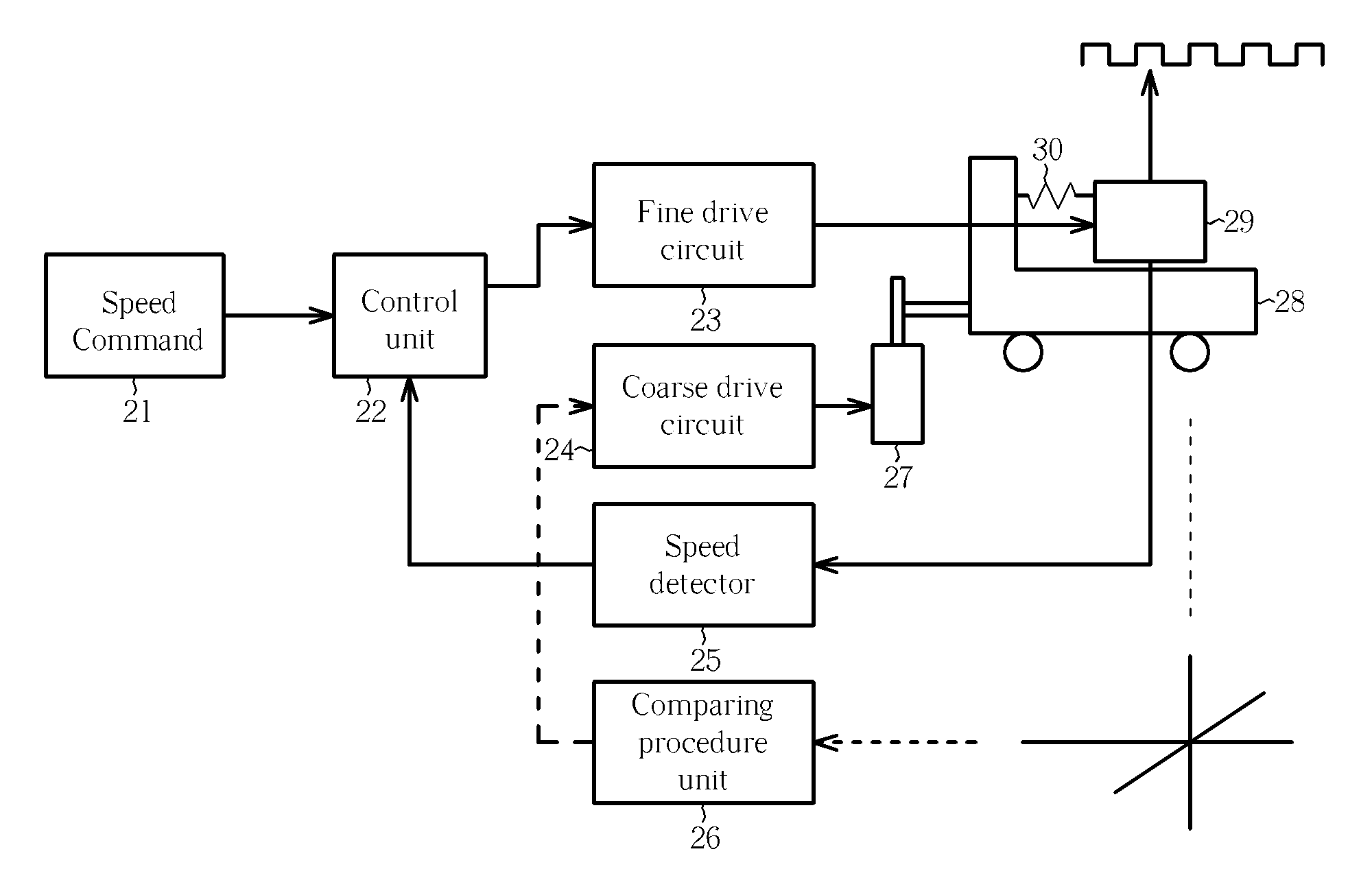
[0029] According to the above-described first embodiment of the track seeking operation of the present invention, by comparing the displacement deviation signal of the fine actuator and the coarse actuator with a predetermined deviation threshold range, if the displacement deviation signal falls outside the predetermined deviation threshold range and is larger than the predetermined deviation threshold range, a fixed value of a characteristic value is utilized to drive the coarse actuator 28, which thereby allows the fine actuator 29 to maintain its position at the center of the coarse actuator 28. This prevents the seeking operation of the fine actuator 29 from failing due to reaching the edge of the coarse actuator 28 and thereby increases the efficiency of track seeking operations.

[0030] Please refer to FIG. 4 showing a flowchart of a track seeking method according to a second exemplary embodiment of the present invention. The track seeking method of the second embodiment also ut...

second embodiment

[0045] In the above second embodiment, after inputting a characteristic value to push the coarse actuator, the adjustment of the coarse actuator is inspected according to a rise or fall of the deviation signal. The rise or fall of the deviation signal is utilized to decide whether to increase or decrease the size of the inputted characteristic value. In this way, coarse actuator is pushed, and the characteristic value is repeatedly adjusted to thereby change the strength of the drive signal. Therefore, in the condition that the optical disc drive cannot smoothly drive the coarse actuator 28 to allow the fine actuator 29 to maintain a position in the center region, the amplitude of the characteristic value is gradually increased. As a result, it is very efficient and accurate to maintain the corresponding positional range between the coarse actuator 28 and the fine actuator 29.

[0046] Using the same logic, in step 416 of the above-described second embodiment, in addition to storing th...


PUM


Abstract

A seeking method of an optical disc drive includes steps of (a) calculating a deviation signal value between a location of a fine actuator and a coarse actuator, (b) judging whether or not the deviation signal value is within a deviation signal threshold interval, (c) outputting a characteristic value to push the coarse actuator if the deviation signal value is not within the deviation signal threshold interval, and (d) jumping to a target track.

Description

BACKGROUND OF THE INVENTION [0001] 1. Field of the Invention [0002] The invention relates to an optical disc drive, and more particularly, to a track seeking method of an optical disc drive. [0003] 2. Description of the Prior Art [0004] Allowing for track seeking operations while reading an optical disc, a typical optical disc drive is composed of a coarse actuator, a sliding carriage, a guided fine actuator, and an object lens. The coarse actuator is controlled from a direct current (DC) motor and a screw, and the feeding range of the coarse actuator is greater than the fine actuator. The fine actuator is coupled to the coarse actuator to thereby create an actuator unit. Normally, the fine actuator is adjusted by a voice coil motor. When the fine actuator skips tracks to the edge of the coarse actuator, in order to continue the seeking operation, the coarse actuator must move and allow the fine actuator to be able to continue performing the seeking operation. If the coarse actuator...

Claims


Application Information

Patent Timeline
IPC IPC(8): G11B7/00
CPCG11B7/08582G11B7/08505
Inventor HSIAO, YI-LONGLIU, AN-TE
Owner QUANTA STORAGE INC
Why Eureka
Eureka Blog
Learn More