Cylindrical grinding method for producing hard metal tools and cylindrical grinding machine for grinding cylindrical starting bodies during the production of hard metal tools

Active Publication Date: 2006-06-08
ERWIN JUNKER MASCHNINENFAB
View PDF12 Cites 5 Cited by
  • Summary
  • Abstract
  • Description
  • Claims
  • Application Information

AI Technical Summary

Benefits of technology

[0005] The object of the invention is therefore to improve the method known from the prior art such

Problems solved by technology

The known methods in accordance with the prior art work satisfactorily, however they entail the risk of errors in the trueness of the run.
These errors are related primarily to multiple instances of re-chucking.
Even if work is performed with great attention to precision, such errors in th

Method used


Image

  • Cylindrical grinding method for producing hard metal tools and cylindrical grinding machine for grinding cylindrical starting bodies during the production of hard metal tools
  • Cylindrical grinding method for producing hard metal tools and cylindrical grinding machine for grinding cylindrical starting bodies during the production of hard metal tools
  • Cylindrical grinding method for producing hard metal tools and cylindrical grinding machine for grinding cylindrical starting bodies during the production of hard metal tools

Examples


Embodiment Construction

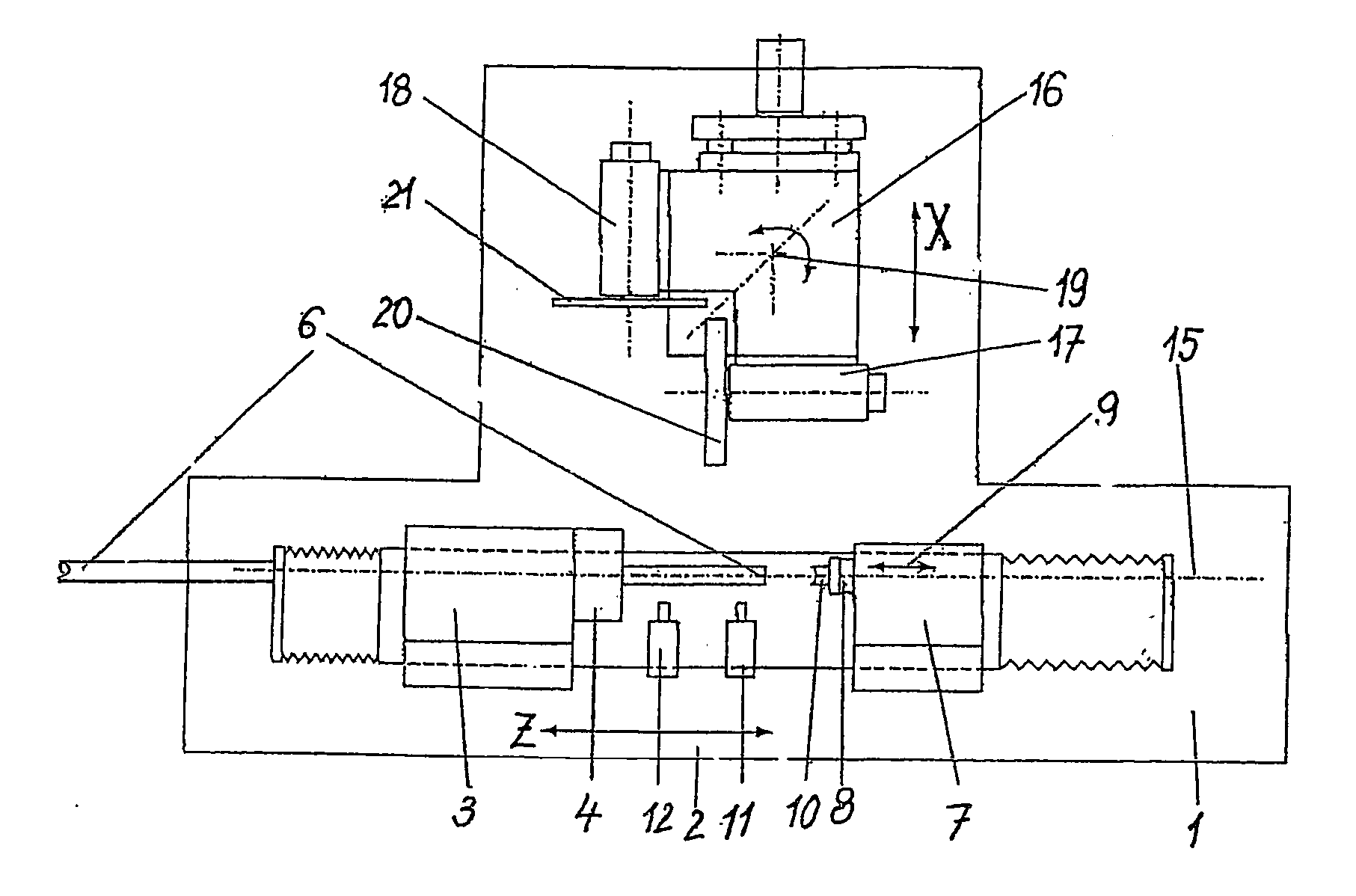
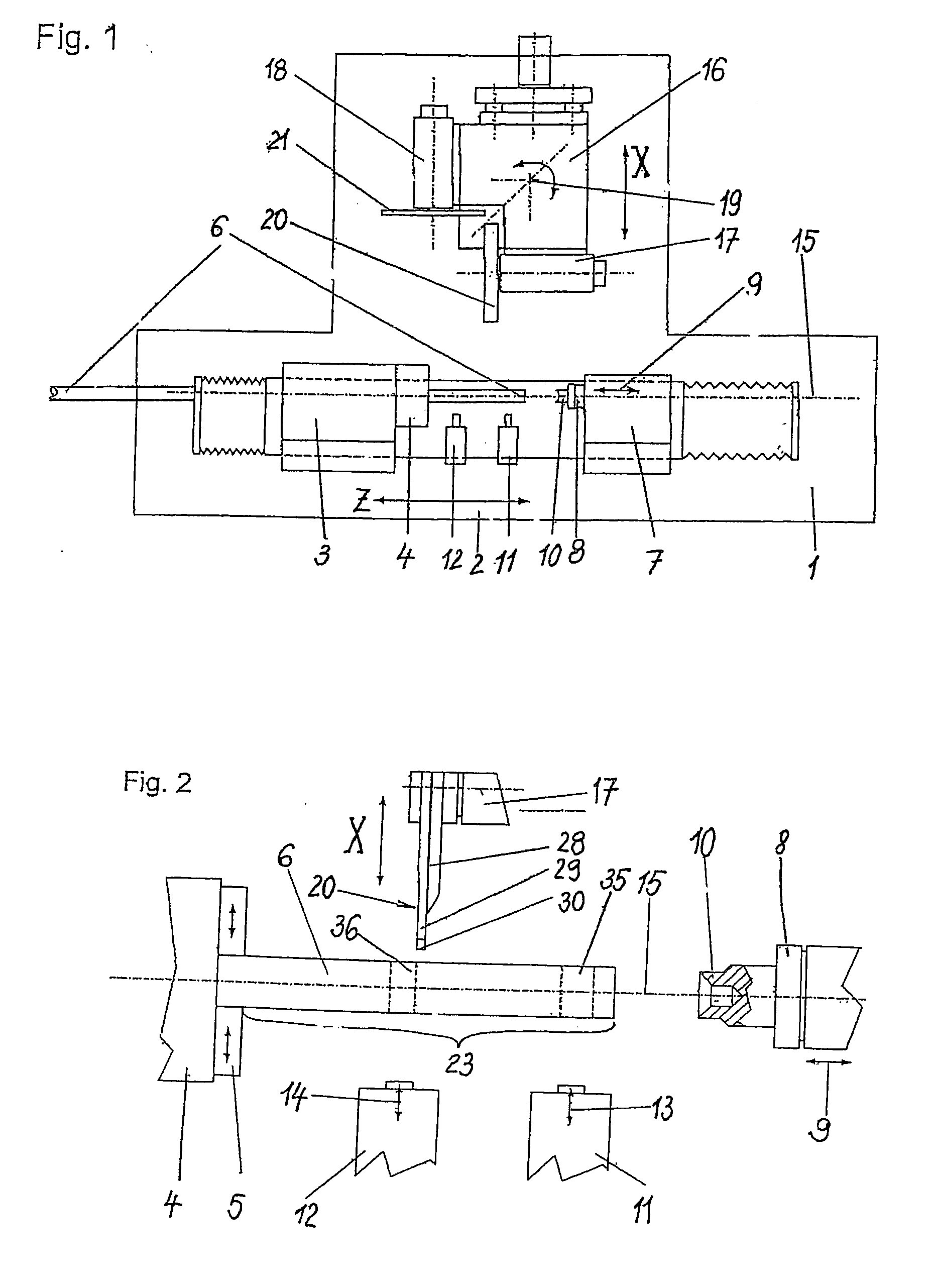
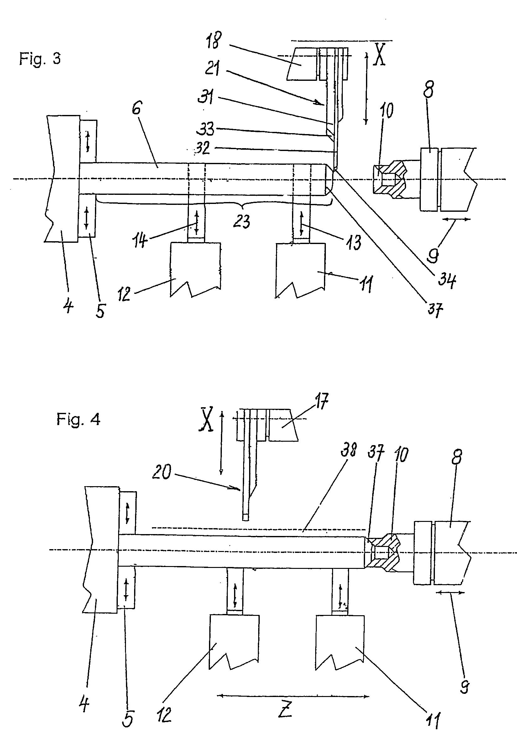
[0050]FIG. 1 is the simplified view from above of a grinding machine for performing the inventive method. The machine bed is labeled with the number 1, and in the front region a grinding table 2 is placed on it. The grinding table 2 can travel in the direction of the axis Z by means of a CNC control. Placed on the grinding table 2 on the left-hand side is a workpiece spindle head 3 that receives a chuck 4 that is driven rotationally by means of an electromotor (not shown). The chuck 4 can be seen at the front of the workpiece spindle head 3. It is used to grip the workpiece, in this case the round rod 6. The chuck 4 is embodied such that the round rod 6 can be moved through the chuck and securely clamped in the desired axial positions by means of the clamping jaws 5 (FIG. 2). Positioned opposite the workpiece spindle head 3 on the grinding table 2 is a tailstock 7 that receives a sleeve 8 that can travel in the axial direction. The arrow 9 indicates the sleeve movement. The exterior...


PUM

PropertyMeasurementUnit
Lengthaaaaaaaaaa
Diameteraaaaaaaaaa
Widthaaaaaaaaaa

Abstract

The invention relates to a grinding method and to a cylindrical grinding machine, in which a sintered hard metal round rod is completely pushed through a chuck of a workpiece spindle head, said chuck having chuck jaws. Two backrest seats are ground on the freely projecting end area of the round rod, and two backrests are then placed on the round rod in directions. The resulting secure support of the end area enables a front cone to be ground with a high level of precision with regard to the concentricity at the end of the round rod facing the quill of a tailstock. A multiple grinding wheel, which is comprised of two differently designed individual wheels that directly rest against one another in an axial manner, serves to grind the front cone and is advanced toward the round rod in the X-direction. The multiple grinding wheel is mounted in a grinding spindle. The individual wheels have different grinding areas. After the front cone has been ground, it is lodged in a hollow punch at the front end of the quill, whereby the quill is displaced toward the front cone in the direction of arrow. The end area of the round rod is hereby optimally fixed at both ends without the first fixing of the chuck having to be released. In this state, the desired cylindrical grinding final contour of the end area can be produced by cylindrical grinding. This procedure is particularly advantageous for producing hard metal tools. By working the rod with a single chucking, machining can be carried out both economically and without the risk of radial deviations. The different individual wheels of the multiple grinding wheel can serve additional different grinding tasks. When the end area has reached the desired concentric final contour, it is cut off from the round rod by the individual wheel.

Description

BACKGROUND OF THE INVENTION [0001] The invention relates to a method for circular grinding during the production of tools made of hard metal on a circular grinding machine that has a workpiece spindle head and a tailstock, whereby work commences using a round rod comprising a starting material. [0002] According to the prior art known from commercial practice, as a rule work commences starting with round rods made of sintered hard metal. These rods then have a grinding overmeasure for the shaft region and are cut to the necessary tool length, or the starting bodies are brought to the required shaft dimension for their entire length using so-called centerless grinding and are then cut into lengths. From the bar pieces that were cut into lengths individually, the tool is then produced from the whole by grinding. For this, the hard metal tools are received during grinding between hollow center punches, tips, or in a chuck. [0003] Grinding occurs either using the conventional grinding me...

Claims


Application Information

Patent Timeline
IPC IPC(8): B24B51/00B24B1/00B24B9/00B24B5/02B24B41/06
CPCB24B5/02B24B41/06B24B5/04
Inventor JUNKER, ERWIN
Owner ERWIN JUNKER MASCHNINENFAB
Why Eureka
Try Eureka