Variable dispersion compensator

Inactive Publication Date: 2007-01-18
HITACHI METALS LTD
View PDF1 Cites 10 Cited by
  • Summary
  • Abstract
  • Description
  • Claims
  • Application Information

AI Technical Summary

Benefits of technology

[0016] The present invention makes it possible to obtain a variable dispersion compensator that has characteristics of a wide frequency band, a low group-delay ripple, and a large variable amount of dispersion. This, in turn, allows simultaneous dispersion compensation of all optical signals during wavelength division multiplex (WDM) transmission, and thus the

Problems solved by technology

The above-described conventional dispersion compensators, however, pose various problems.
Additionally, since the dispersion compensation fiber is usually small in mode field diameter, the fiber produces a significant optical-fiber nonlinear effect and is thus likely to distort transmission waveforms.
It is therefore known that when used for dispersion compensation, these gratings are inferior to dispersion compensation fibers in transmission characteristics.
Also, there are manufacturing-associated problems in that gratings large in the amount of dispersion or wide in wavelength band cannot be easily produced and in that gratings narrow in band require the stabilization of temperature and wavelength.
In addition, with a dispersion compensation fiber, the amount of dispersion cannot be continuously ma

Method used


Image

  • Variable dispersion compensator
  • Variable dispersion compensator
  • Variable dispersion compensator

Examples


Example

[0058] Embodiments of the present invention will be described in detail hereunder using the accompanying drawings.

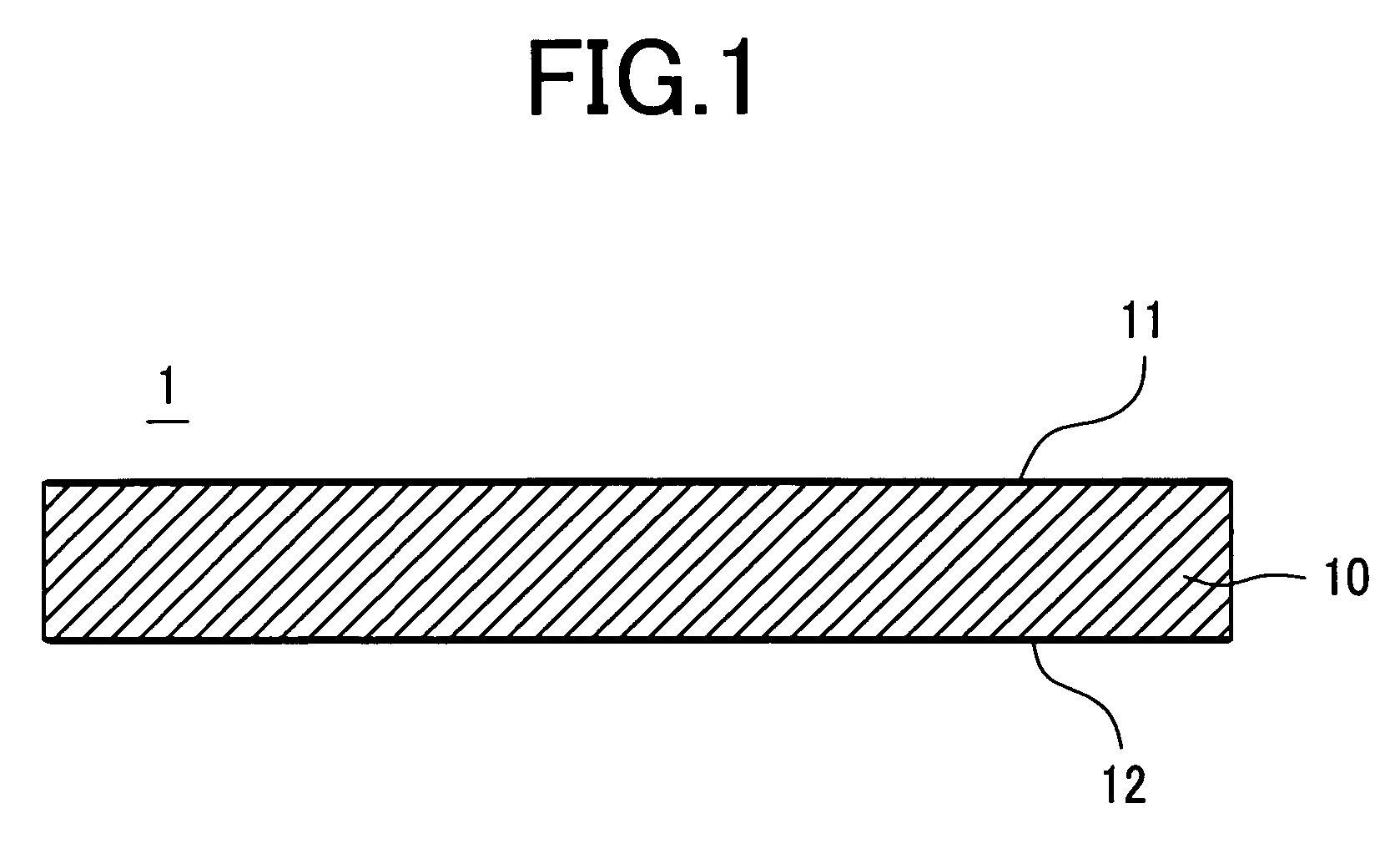
[0059] First, an etalon is described. A cross-sectional structure of the etalon is shown in FIG. 1. Reference number 1 denotes the etalon, which includes a precisely parallelized planar plate 10 having upper and lower faces coated with reflecting films 11, 12, respectively. Metal films made of gold, silver, or other high-reflectance metallic materials, dielectric multi-layer films, or the like, are used as the reflecting films. In particular, an etalon having ideally an amplitude reflectance of 100% on one face is called the GT etalon, which was named after Gires and Tournois, the proposers. In reality, however, it is difficult to obtain an amplitude reflectance of 100%, so the reflecting films may be allowed to have an amplitude reflectance of at least about 90%. In addition, the amplitude reflectance of one reflecting film does not need to be too high when the film is...


PUM


Abstract

A resonator-type variable dispersion compensator is provided which is effective for practical use with a wavelength division multiplex transmission system. The dispersion compensator is constructed so as to shift a variable range to the plus or minus side according to the particular specifications of a transmission line. The dispersion compensator with an etalon and a mirror arranged in parallel or at a slight angle with respect to each other is constructed so that emitted light from a collimator is reflected by the etalon multiple times and then enters another collimator. The dispersion compensator also has dispersion compensating units that change temperature using a heater or equivalent in order to render the amount of dispersion variable. In addition, these dispersion compensating units are provided in multi-stage form, and the angle of the mirror, the amplitude reflectance of the etalon, and temperature are optimized to offer polygonal dispersion characteristics. This realizes a practical, variable dispersion compensator suitable for a wavelength division multiplex optical transmission system and capable of shifting a variable amount of dispersion to the plus or minus side.

Description

CROSS-REFERENCE TO RELEVANT APPLICATION [0001] The disclosure of the patent application Ser. No. 11 / 177,372, filed on Jul. 11, 2005, pending in THE UNITED STATES PATENT AND TRADEMARK OFFICE, has been incorporated by reference into the present application. CLAIM OF PRIORITY [0002] The present application claims priority from Japanese application JP 2005-202570 filed on Jul. 12, 2005, the content of which is hereby incorporated by reference into this application.FIELD OF THE INVENTION [0003] The present invention relates to variable dispersion compensators, and more particularly, to an optical dispersion compensator suitable for application to optical transmission systems employing an optical fiber, and systems employing an optical transmission scheme based on wavelength division multiplexing. BACKGROUND OF THE INVENTION [0004] Research and development activities on the long-distance optical transmission systems that use optical amplifiers as repeaters, have been actively performed in...

Claims


Application Information

Patent Timeline
IPC IPC(8): G02B6/26G02B26/06
CPCG02B6/29358G02B6/29398G02B6/29395G02B6/29394
Inventor SUGAWARA, TOSHIKIMAKIO, SATOSHI
Owner HITACHI METALS LTD
Why Eureka
Try Eureka