Eureka AIR delivers breakthrough ideas for toughest innovation challenges, trusted by R&D personnel around the world.

Method and apparatus for providing automatic lane calibration in a traffic sensor

Active Publication Date: 2007-01-18
IMAGE SENSING SYSTEMS
View PDF20 Cites 24 Cited by
  • Summary
  • Abstract
  • Description
  • Claims
  • Application Information

AI Technical Summary

Problems solved by technology

As urban centers increase in size, and traffic congestion becomes increasingly a problem, there is a concomitant increasing need for current and accurate traffic statistics and information.
Inductive loop sensors, which are installed under the pavement, are expensive to install, replace and repair, both in terms of roadwork required and in terms of the disruption to traffic.
However, this is expensive both in terms of paying the technician, and due to the resulting disruption of traffic.

Method used


Image

  • Method and apparatus for providing automatic lane calibration in a traffic sensor
  • Method and apparatus for providing automatic lane calibration in a traffic sensor
  • Method and apparatus for providing automatic lane calibration in a traffic sensor

Examples


Embodiment Construction

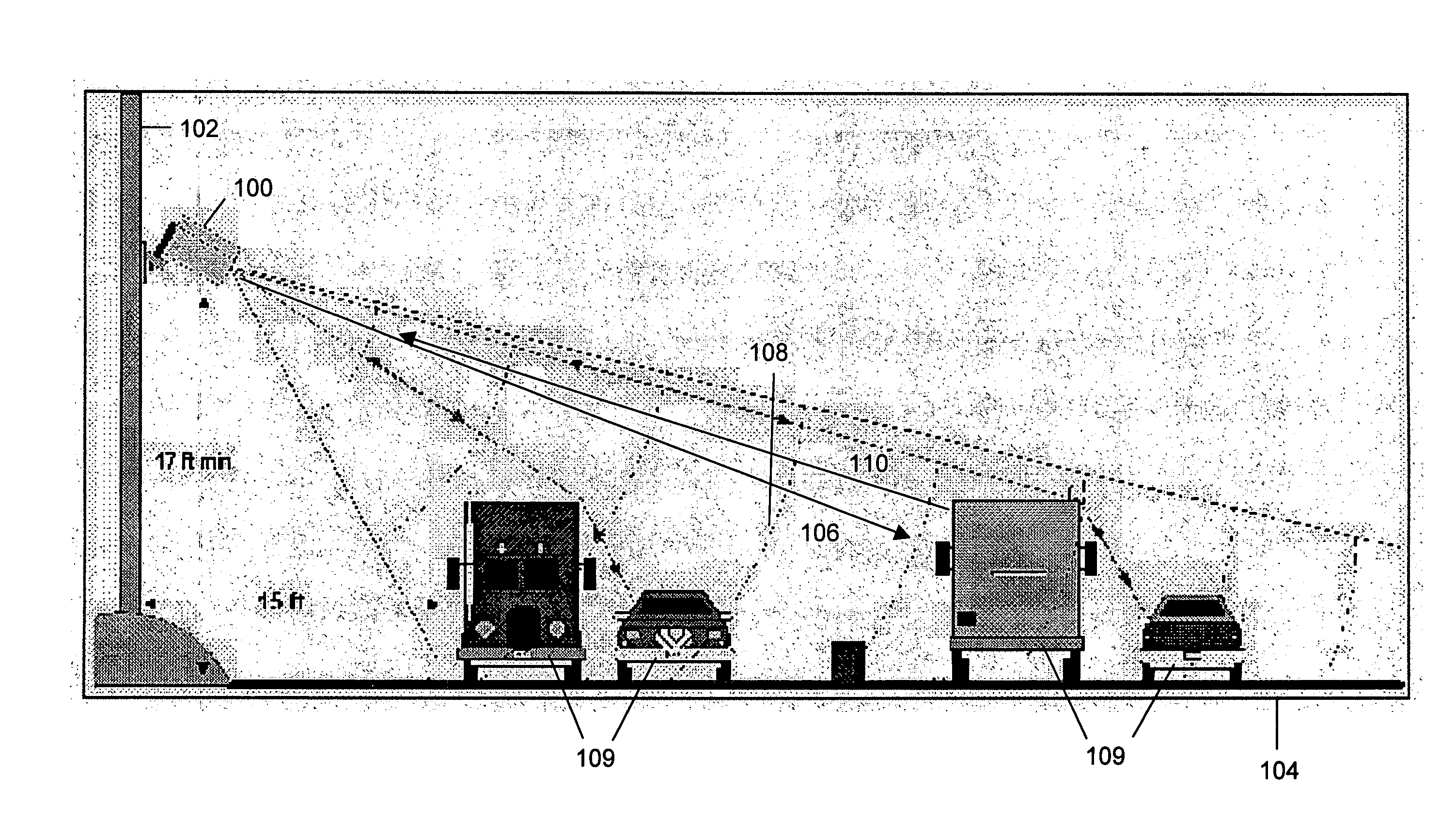
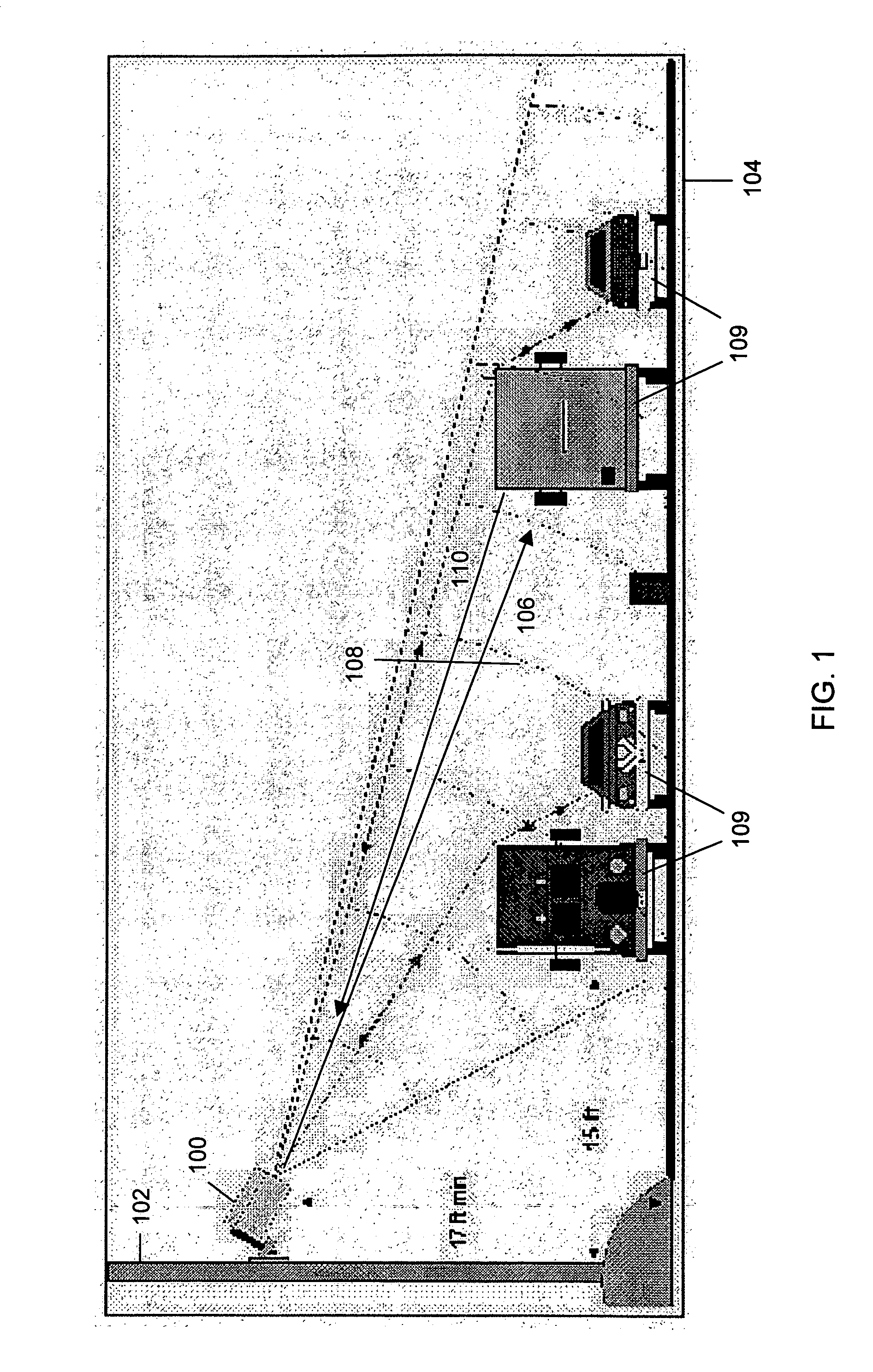
[0015] Referring to FIG. 1, there is illustrated in a schematic view, a sensor 100 in accordance with a preferred aspect of the present invention. The sensor 100 is mounted on a pole 102 in a side-mounted configuration relative to road 104. Sensor 100 transmits a signal 106 through a field of view 108 at the road 104 to “paint” a long elliptical footprint on the road 104. Any non-background targets, such as vehicles 109, reflect a reflected signal Pr 110 having power level P. Specifically, the low-power microwave signal 106 transmitted by sensor 100 has a constantly varying frequency. Based on the frequency of the reflected signal 110, the sensor can determine when the original signal was transmitted, thereby determining the time elapsed and the range to the reflecting object. The range of this reflected object is the “r” in Pr.

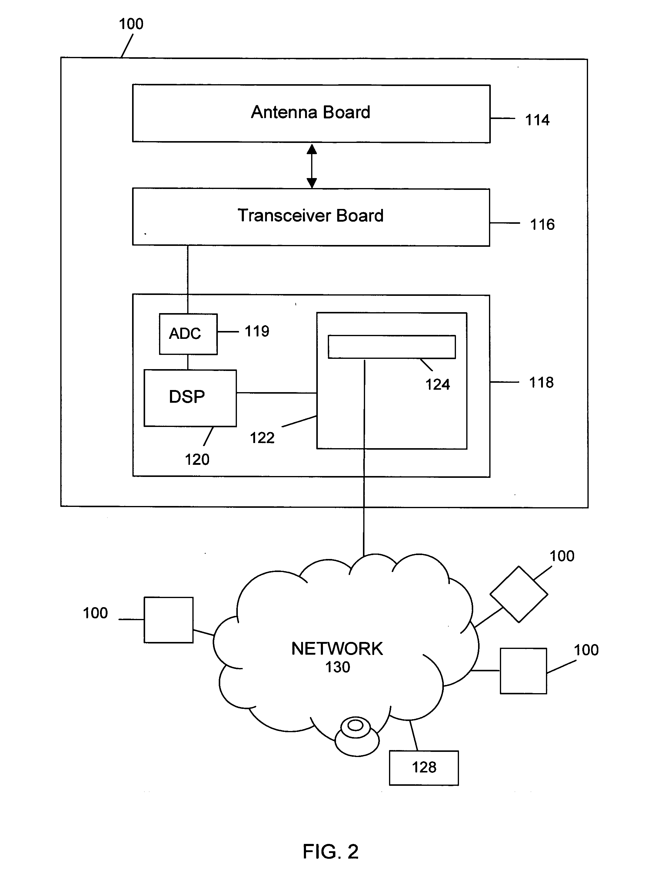
[0016] Referring to FIG. 2, the components of the sensor 100 are illustrated in a block diagram. As shown, the sensor 100 comprises an antenna board 114 for...


PUM


Abstract

A method of operating a traffic sensor to define ranges of centers of traffic lanes from the traffic sensor is described. The method comprises a) providing a set of lane center variables representing the ranges of the centers of the traffic lanes from the traffic sensor; b) initializing each lane center variable in the set of lane center variables to have an associated starting range value; and then, c) updating the set of lane center variables by, for each vehicle in a plurality of vehicles, i) detecting the vehicle, ii) determining an associated lane center variable having an associated lane center range value closest to the vehicle; iii) estimating a vehicle displacement from the associated lane center range value, and iv) calculating a new lane center range value for the associated lane centre variable using the associated lane center range value and the vehicle displacement.

Description

FIELD OF THE INVENTION [0001] The present invention relates in general to traffic sensors, and more particularly relates to the calibration of traffic sensors based on a range or distance of vehicles measured from the traffic sensor. BACKGROUND OF THE INVENTION [0002] As urban centers increase in size, and traffic congestion becomes increasingly a problem, there is a concomitant increasing need for current and accurate traffic statistics and information. Traffic surveillance relies primarily upon traffic sensors, such as (1) inductive loop traffic sensors, which are installed under the pavement; (2) video sensors; (3) acoustic sensors; and, (4) radar sensors. Inductive loop sensors, which are installed under the pavement, are expensive to install, replace and repair, both in terms of roadwork required and in terms of the disruption to traffic. In contrast, video sensors, acoustic sensors and radar sensors are easier to install, replace and repair. They have the added advantage of mu...

Claims


Application Information

Patent Timeline
IPC IPC(8): G08G1/00
CPCG08G1/167G08G1/048
Inventor MANOR, DAN
Owner IMAGE SENSING SYSTEMS
Why Eureka
Eureka Blog
Learn More