
Connector for tent pole

Inactive Publication Date: 2007-01-25
LAH JEH KUN
View PDF0 Cites 7 Cited by
  • Summary
  • Abstract
  • Description
  • Claims
  • Application Information

AI Technical Summary

Benefits of technology

[0011] Accordingly, the present invention has been made to solve the above problems. An object of the present invention is to provide a connector for a tent pole capable of preventing a tent pole from being damaged at a connection region of a tent pole and the connector and minimizing a weight increase even when the plurality of tent poles are connected.
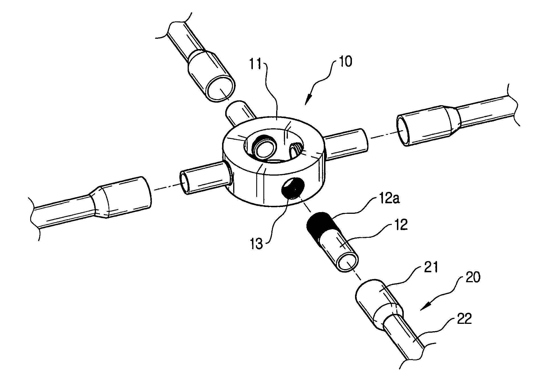
[0012] In order to achieve the above object, there is provided a connector for connecting a plurality of tent poles constituting a frame of a tent, the connector having a tubular body and a plurality of insert poles connected radially to the body and inserted into one end of the tent pole. A plurality of tap holes are formed along a periphery of the body at an interval and an external screw portion corresponding to the tap hole is formed on one end of the insert pole, so that the insert pole is screw-engaged to the tap hole. According to the above connector for the tent pole, since the tent pole is connected to the connector through the insert hole without being directly connected to the connector, it is possible to minimize a size and a weight of the connector and to prevent the tent pole from being damaged at a connection region with the connector when bending stress is applied to the region.
[0013] According to an embodiment of the invention, an enlarged portion having a large diameter may be formed on one end of the tent pole into which the insert pole is inserted. In this case, the insert pole has an outer diameter corresponding to an inner diameter of the enlarged portion. Like this, when the end of the tent pole is formed with the enlarged portion, since an inertia moment can be increased at the connection region with the insert pole, it is possible to prevent the tent pole from being damaged when the bending stress is applied, more positively.
[0015] In the mean time, according to another embodiment of the invention, the insert poles may be arranged to the body in two or more rows in a vertical direction. By doing so, since it is possible to minimize a diameter increase of the body when connecting the tent poles with the connector, the weight increase of the whole connector can be minimized.

Problems solved by technology

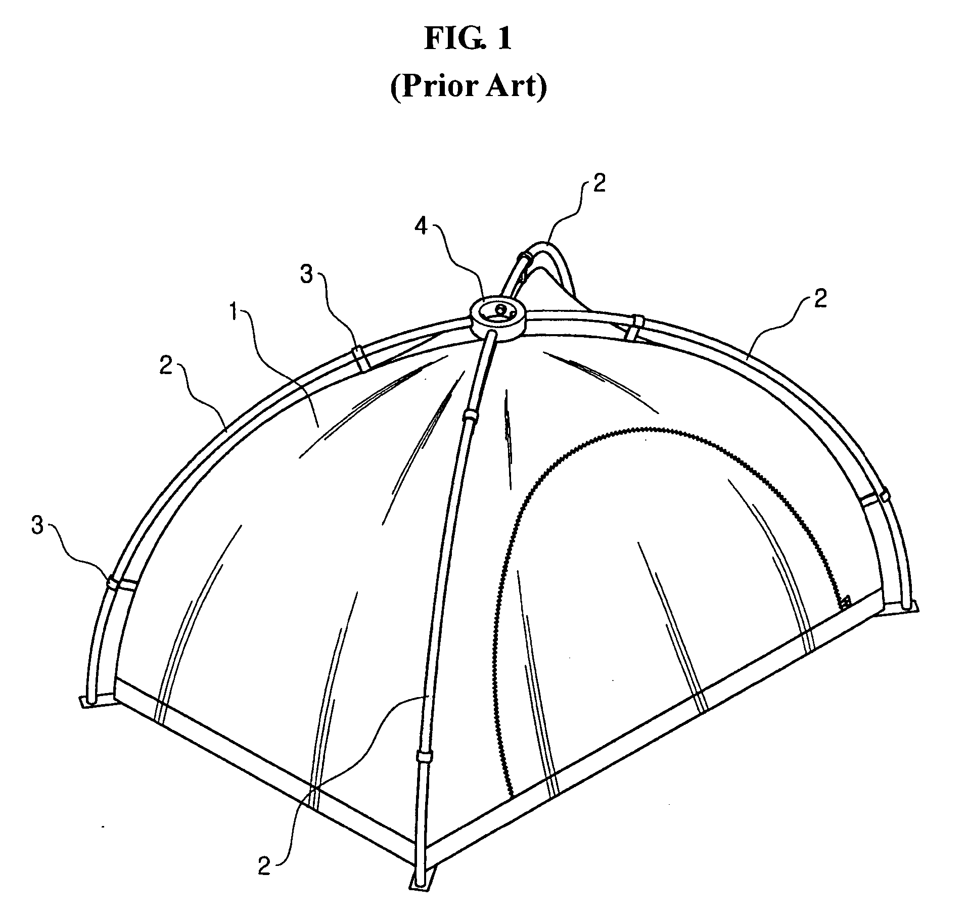
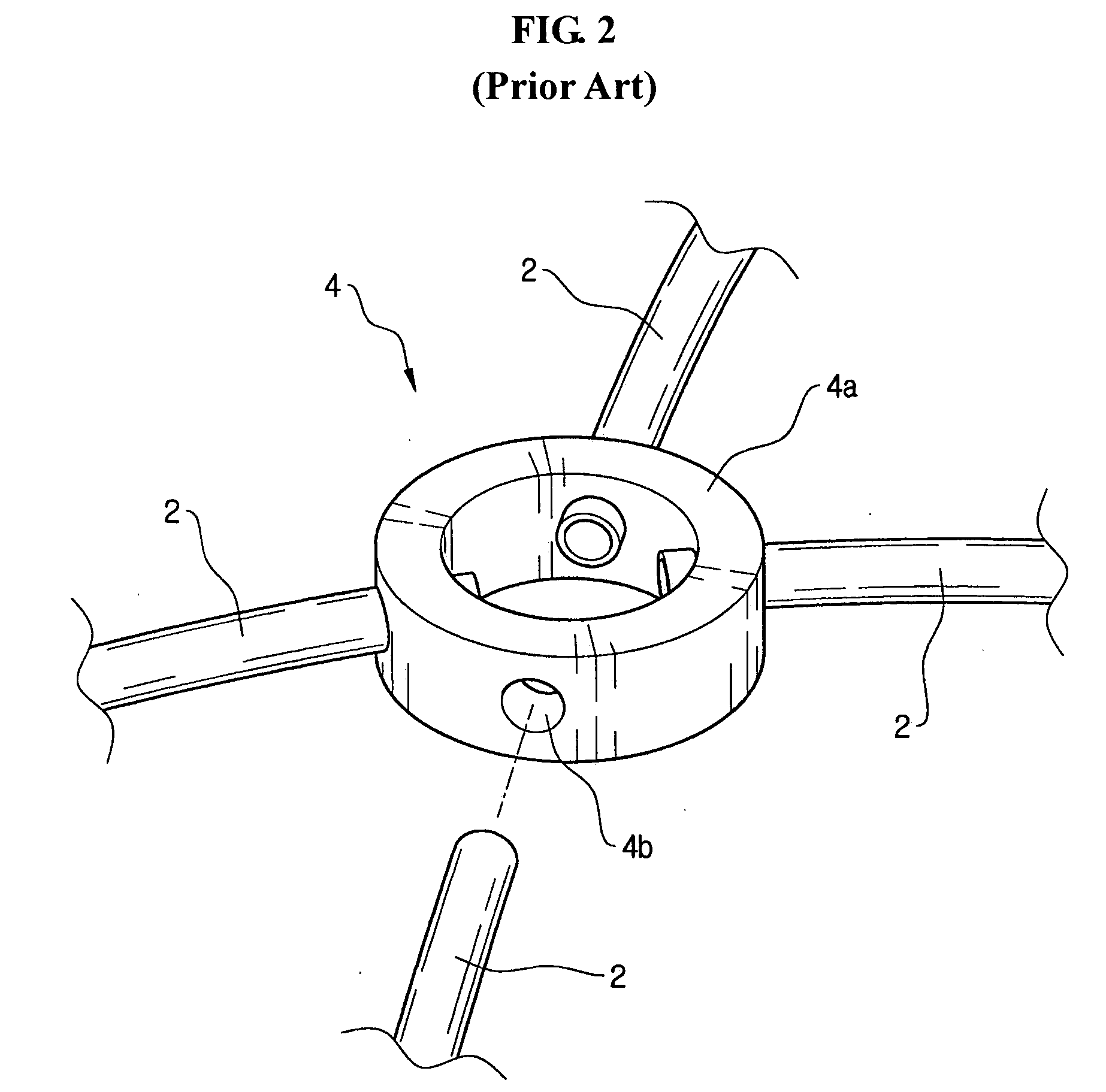
However, according to the connector 4 of the prior art, since bending stress is intensively applied to a connection region (“A” in FIG. 3) of the tent pole 2 and the connector 4, the tent pole 2 is frequently damaged at the region.

Method used


Image

  • Connector for tent pole
  • Connector for tent pole
  • Connector for tent pole

Examples


Embodiment Construction

[0023] Hereinafter, preferred embodiments of the present invention will be described with reference to the accompanying drawings. In the following description of the present invention, a detailed description of known functions and configurations incorporated herein will be omitted when it may make the subject matter of the present invention rather unclear.

[0024] As shown in FIG. 4, a connector 10 for a tent pole according to an embodiment of the invention has a tubular body 11 and a plurality of insert poles 12 connected radially to a periphery of the body 11. An outer diameter of the insert pole 12 is made to be smaller than an inner diameter of a tent pole 20. Each of the insert poles 12 is inserted into one end of the tent pole 20, so that the plurality of tent poles 20 are radially connected to each other through the connector 10. In FIG. 4, it is shown that the connector 10 is provided with the four insert poles 12 and the four tent poles 20 are connected to the connector 10. ...


PUM


Abstract

A connector for connecting tent poles has a tubular body and a plurality of insert poles connected radially to the body and inserted into one end of the tent pole. A plurality of tap holes are formed along a periphery of the body at an interval and an external screw portion corresponding to the tap hole is formed on one end of the insert pole, so that the insert pole is screw-engaged to the tap hole. According to the invention, the tent poles are connected to the connector via the insert poles without being directly connected to the connector. Accordingly, it is possible to minimize the size and the weight of the connector and to prevent the tent pole from being damaged at the connection region with the connector when the bending stress is applied to the region.

Description

CROSS-REFERENCE TO RELATED APPLICATION [0001] This application claims all benefits of Korean Patent Application No. 10-2005-66623, filed on Jul. 22, 2005 in the Korean Intellectual Property Office, the disclosures of which is incorporated herein by reference. BACKGROUND OF THE INVENTION [0002] 1. Field of the Invention [0003] The present invention relates to a connector for connecting a plurality of tent poles, and more particularly to a connector capable of minimizing a weight and preventing a tent pole from being damaged at a connection region with the connector. [0004] 2. Background of the Related Art [0005] In general, a tent forms a dome shape having a certain volume made by assembling waterproof fabrics and a plurality of tent poles, so that it provides a user with a space in which the user can temporarily reside out of doors during the mountain climbing or camping. [0006] When assembling the tent, a connector is often used to easily connect the tent poles. FIG. 1 is a perspec...

Claims


Application Information

Patent Timeline
IPC IPC(8): E04H15/36
CPCE04H15/32E04H15/60E04H15/42E04H15/44
Inventor LAH, JEH-KUN
Owner LAH JEH KUN
Learn More