Method and system for automatic beam allocation in a multi-room particle beam treatment facility

Inactive Publication Date: 2007-01-25
ION BEAM APPL
View PDF4 Cites 183 Cited by
  • Summary
  • Abstract
  • Description
  • Claims
  • Application Information

AI Technical Summary

Benefits of technology

[0009] According to the method of the invention, the MCR-operator does not intervene in the allocation of the relevant beam line. Instead, when the beam is available, the allocation takes place automatically. If the beam is not available, the request is automatically put on a waiting list (queued). The position of the request on the list, i.e. the order in which the requests are l

Problems solved by technology

However, this document does not discuss the problem of allocating the beam when multiple beam requests are issued with various characteristics and requirements
The known manual mode holds a risk of human error.
Also, an optimum use of the various treatment rooms is not guaranteed, nor is it certain that the MCR

Method used


Image

  • Method and system for automatic beam allocation in a multi-room particle beam treatment facility
  • Method and system for automatic beam allocation in a multi-room particle beam treatment facility
  • Method and system for automatic beam allocation in a multi-room particle beam treatment facility

Examples


Embodiment Construction

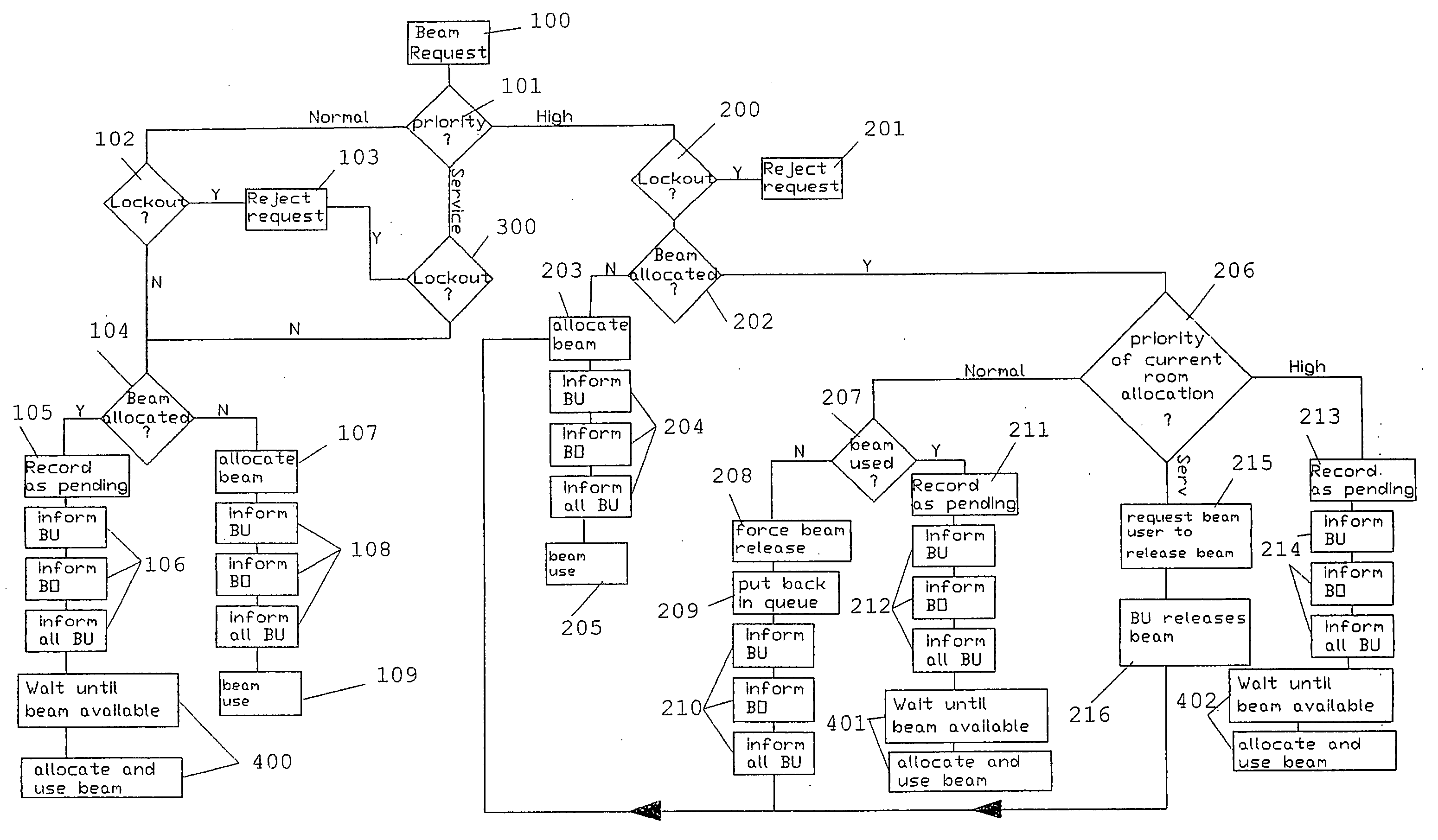
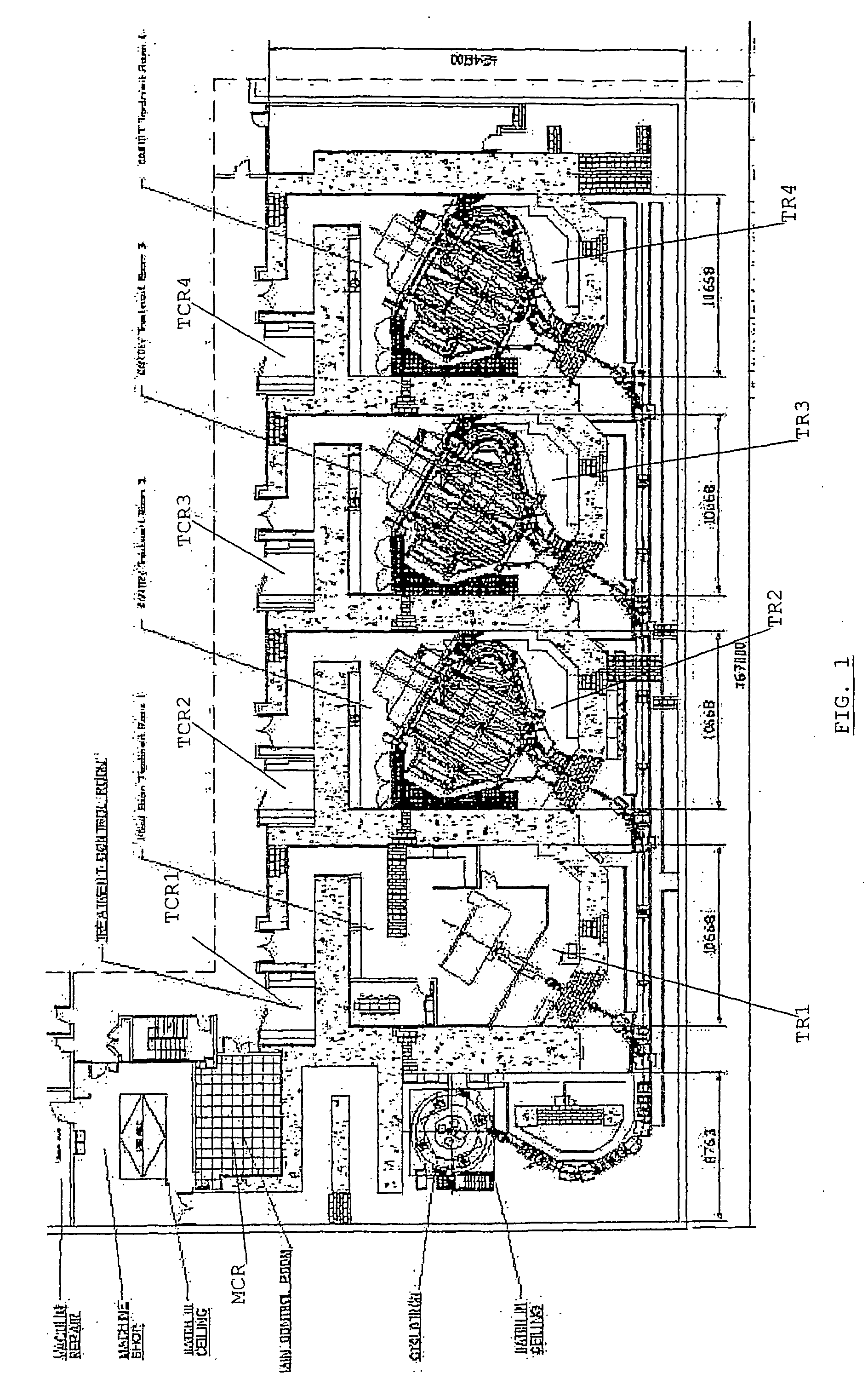
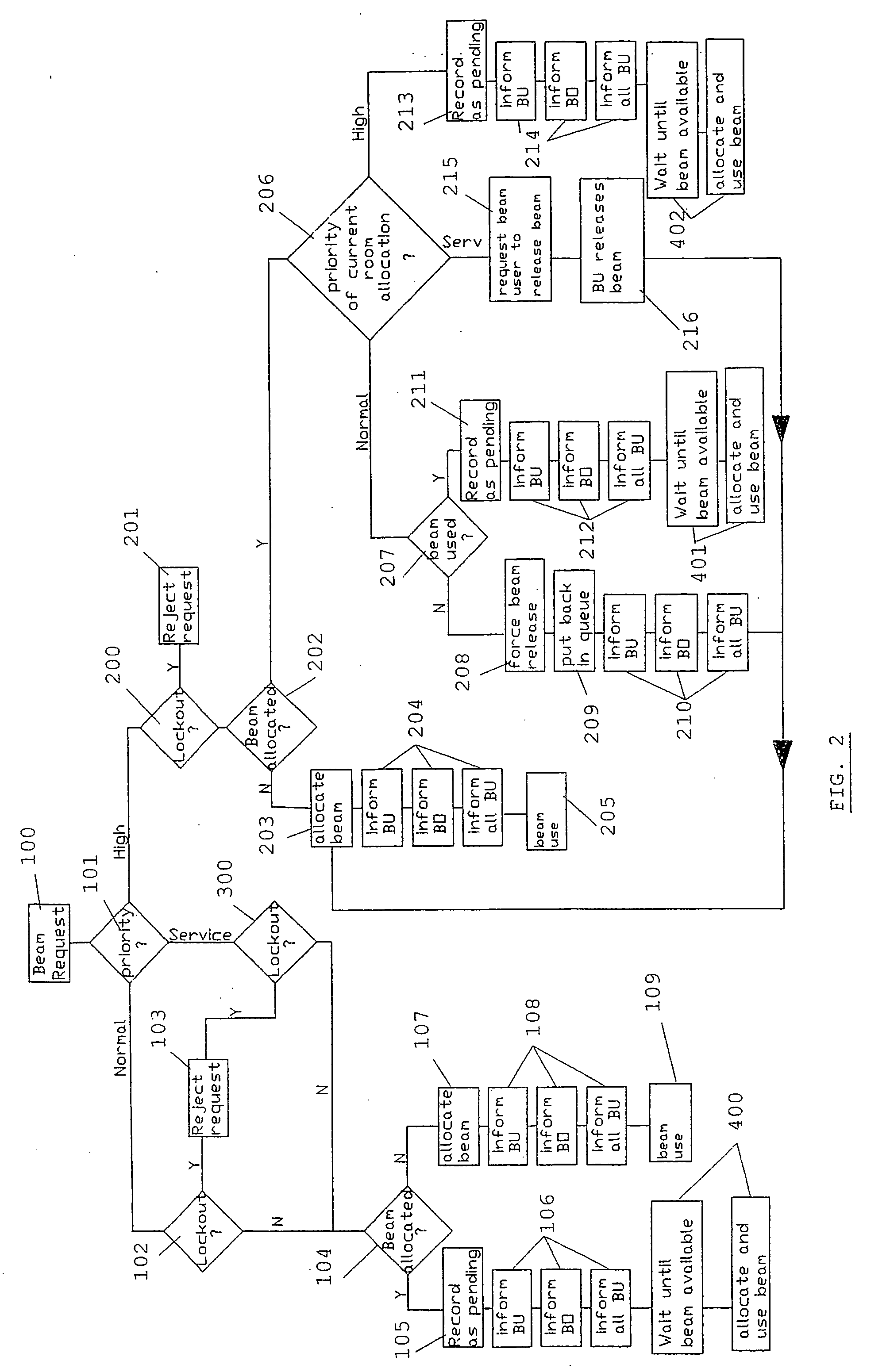
[0015] The invention is related to a method and system for performing automatic allocation of a particle beam in a facility such as the one shown in FIG. 1 (possibly with a different number of treatment rooms). A special feature of the invention concerns the automatic termination of the allocation, under predefined circumstances. As seen in FIG. 1, a Treatment Control Room (TCR1 to TCR4) is present next to each Treatment Room (TR1 to TR4). In every TCR / TR a Beam User may be active who may request the beam for use and use it for treating a patient. The beam user may launch the beam request or other communications from an interface screen in the TCR or from a second screen in the TR. For the purposes of this invention, it is not important whether two screens are available (one in the TCR and one in the TR). It could be sufficient to have one screen in the TCR. What is important is that the beam user is provided with at least one interface screen from which to communicate with the Main...


PUM


Abstract

The present invention is related to a method and a system for automatically allocating a particle beam to one of a plurality of treatment rooms. Upon receiving a request from one of the beam users, the system checks whether the beam is available and may automatically allocate the beam to the requesting room. Otherwise, the request may be put on a waiting list of pending requests, in a position which depends on the priority level (and arrival lime) coupled to said request.

Description

FIELD OF THE INVENTION [0001] The present invention is related to a method and accompanying software, as well as a system for scheduling a beam in multi-room particle beam treatment facilities. STATE OF THE ART [0002] Particle beam treatment, in particular proton beam treatment, is widely used in medical environments. Facilities offering such treatments often consist of one beam source, such as a cyclotron, and a plurality of treatment rooms, each equipped for example with a rotary gantry or a fixed beam apparatus for irradiating a patient who is positioned inside the treatment room. Beam transport lines connect the cyclotron with the treatment rooms. Such beam lines consist of a succession of magnets for conditioning and deflecting the beam and guiding it towards one of the treatment rooms. [0003] In existing facilities, the allocation of the beam to a treatment room is performed manually. With allocation is meant the selecting of a particular beam line through which an irradiation...

Claims


Application Information

Patent Timeline
IPC IPC(8): A61N5/06A61N5/10
CPCA61N5/10A61N2005/1087A61N2005/1074A61N5/1079
Inventor LEYMAN, DIDIERTHIRIONET, PHILIPPEDECROCK, PATRICKFLORQUIN, RENAUD
Owner ION BEAM APPL
Why Eureka
Try Eureka