Nonvolatile latch circuit and system on chip with the same

a latch circuit and non-volatile technology, applied in the direction of information storage, static storage, digital storage, etc., can solve the problem of inability to restore data

Active Publication Date: 2007-01-25
SK HYNIX INC
View PDF6 Cites 50 Cited by
  • Summary
  • Abstract
  • Description
  • Claims
  • Application Information

AI Technical Summary

Benefits of technology

The present invention provides a way for a computer chip or other electronic device to remember its previous state even when it has been turned off and then turn back on again. This happens through a special type of memory called a nonvolatile latch circuit that can sense changes in data during certain periods and quickly store new data without needing another step like starting up the whole machine first.

Problems solved by technology

The technical problem addressed in this patent relates to reducing power consumption of a semiconductor chip used by a nanoscale device. This is achieved by cutting off power supply of the chip in a standby mode but there may still be some leakage currents even at small devices sizes. To address this issue, a nonvolatile latch circuit has been developed that includes multiple components such as inverters, NMOS transistors, and capacitors to store and retrieve previous circuit state without being affected by any accidents like power loss or other factors that might lead to data destruction.

Method used


Image

  • Nonvolatile latch circuit and system on chip with the same
  • Nonvolatile latch circuit and system on chip with the same
  • Nonvolatile latch circuit and system on chip with the same

Examples


Embodiment Construction

[0030] The present invention will be described in detail with reference to the accompanying drawings. Wherever possible, the same reference numbers will be used throughout the drawings to refer to the same or like part.

[0031]FIG. 4 is a diagram illustrating a system on a chip including a nonvolatile latch circuit according to an embodiment of the present invention.

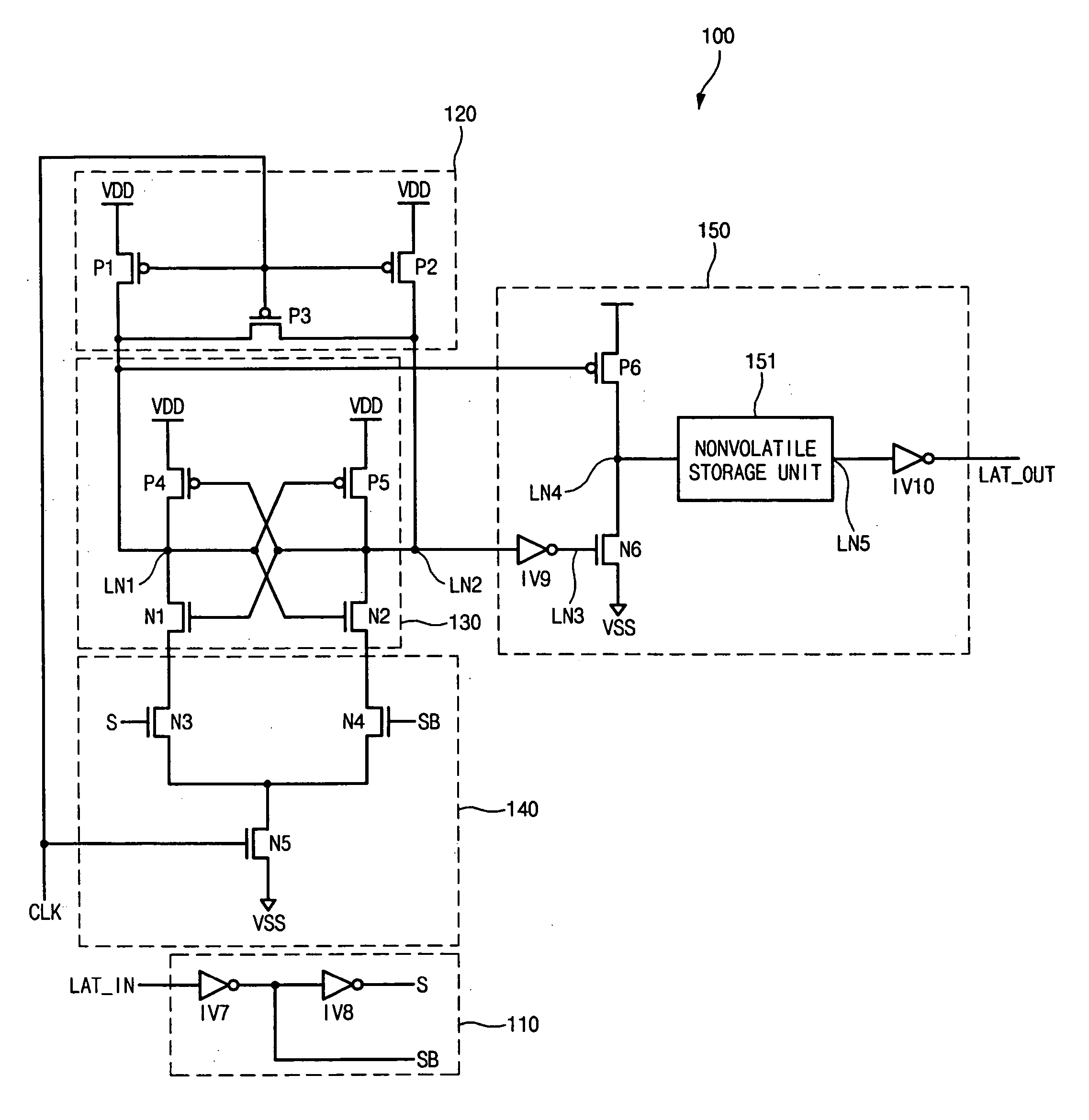
[0032] In this embodiment, a nonvolatile latch NVL positioned in each circuit region of a system on a chip (hereinafter, referred to as “SOC”) stores a logic state of a turn-on state of a power supply switch in a power-off operation of the power supply switch.

[0033]FIG. 5 is a diagram illustrating a data storage / recall method of the nonvolatile latch circuit according to an embodiment of the present invention.

[0034] In this embodiment, an additional data storage period before entry of the power-off mode is not required. The change of latch data is detected in an active period, a latch transition detecting signal LTD is...


PUM


Abstract

A nonvolatile latch circuit and a system on a chip with the same feature detection of change of latch data in an active period to store new data in a latch without an additional data storage time. The nonvolatile latch circuit does not require an additional data storage period but detects change of latch data in the active period to store new data in a nonvolatile latch unit. When power is accidentally off, new data are constantly stored in the nonvolatile latch unit, thereby preventing data loss and improving an operating speed without a booting time for restoring data.

Description


Claims


Application Information

Patent Timeline
Owner SK HYNIX INC
Why Eureka
Try Eureka