
Video encoding and decoding methods and corresponding devices

a video and encoding technology, applied in the field of video compression, can solve the problems of blocking artifacts, inability to deliver an artefact-free sequence, and visible prediction grids

Inactive Publication Date: 2007-01-25
DYNAMIC DATA TECH LLC
View PDF0 Cites 26 Cited by
  • Summary
  • Abstract
  • Description
  • Claims
  • Application Information

AI Technical Summary

Problems solved by technology

However, at low bitrates, the hybrid motion compensated DCT structure may be not able to deliver an artefact-free sequence for two reasons.
First, the structure of the motion-compensated inter prediction grid becomes visible, with blocking artifacts.
Moreover, the block edges of the DCT basis functions become visible in the image grid, because too few coefficients are quantized—and too coarsely—to make up for these blocking artifacts and to reconstruct smooth objects in the image.
Moreover, since overlapped motion compensation is no longer mandatory to preserve the MP efficiency, classical motion compensation may be used.
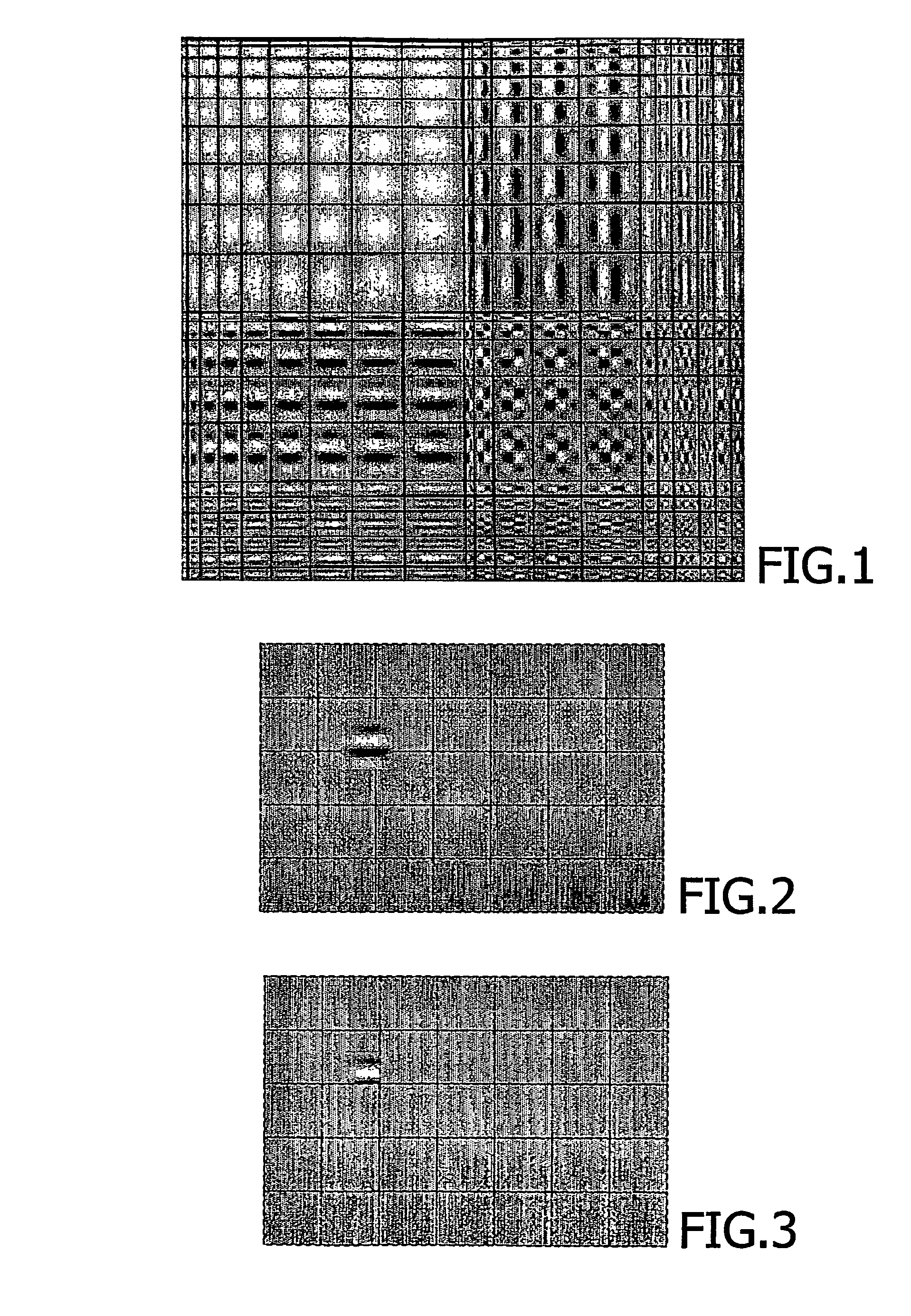
However, with such an approach, it is not sure that the dictionary is well adapted to the structure of the signal to be modelled, when its atoms are confined in arbitrarily sized blocks.

Method used


Image

  • Video encoding and decoding methods and corresponding devices
  • Video encoding and decoding methods and corresponding devices
  • Video encoding and decoding methods and corresponding devices

Examples


Embodiment Construction

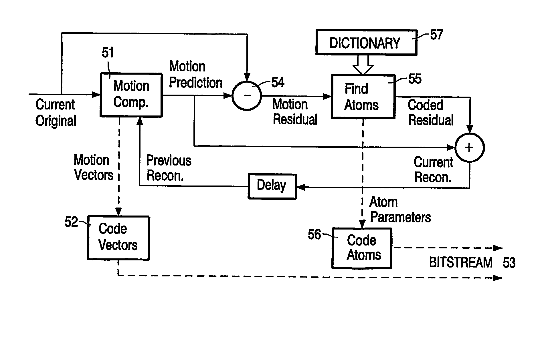
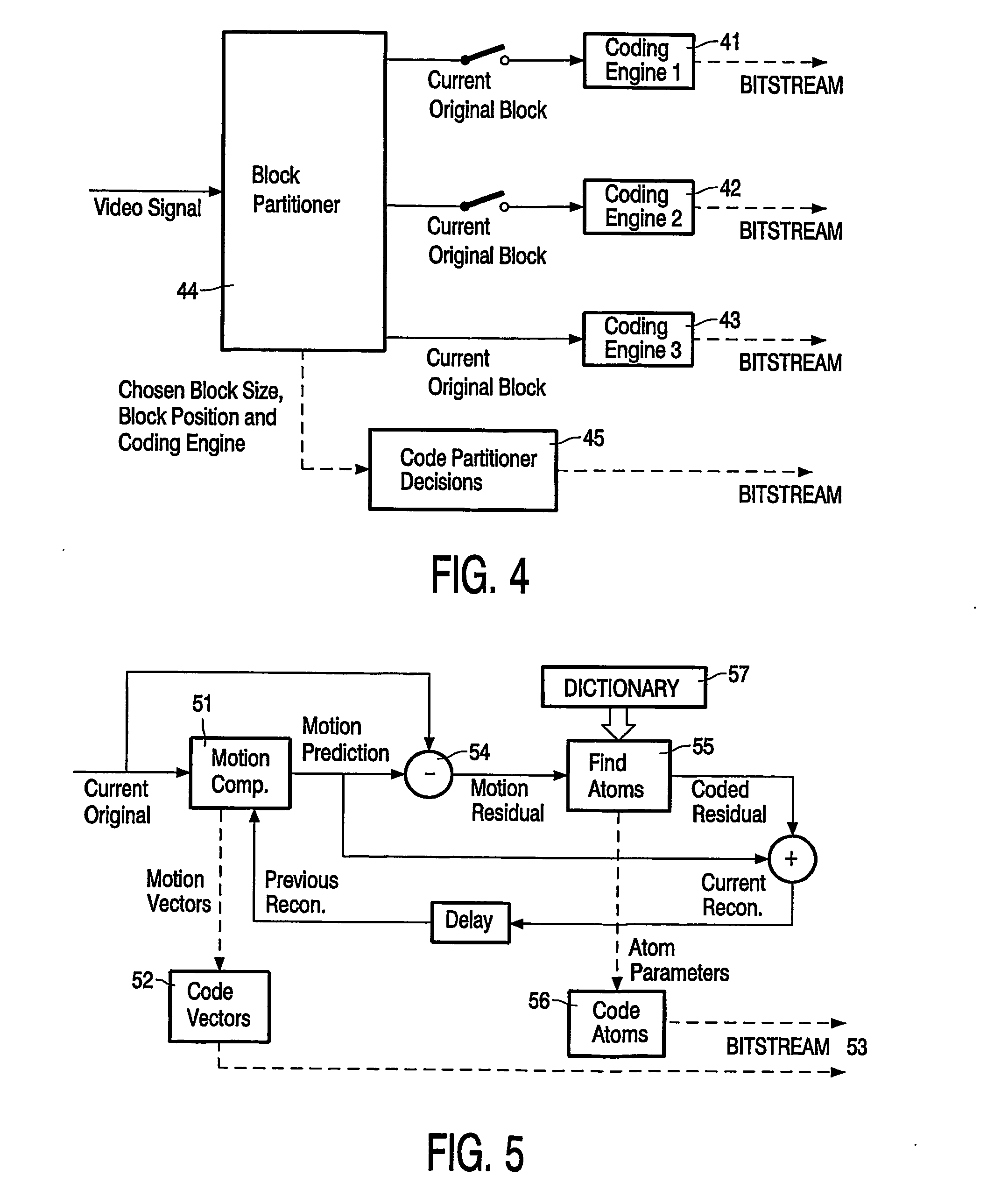
[0039] A simplified block diagram of a video encoding device implementing a matching pursuit algorithm has been described above in relation with FIG. 5. This encoding device carries out a method of coding an input bitstream that comprises the same steps as described above: [0040] the original frames of the input sequence are motion-compensated; [0041] residual signals are generated by difference between the current frame and the associated motion-compensated prediction; [0042] each of said residual signals is compared with a dictionary of functions consisting of a collection of 2D separable Gabor functions; [0043] once the atom parameters are found, they can be coded (together with the motion vectors previously determined), the coded signals thus obtained forming the bitstream sent to the decoder.

[0044] The technical solution now proposed according to the invention consists in having separate dictionaries, one for each block shape respectively (4×4, 4×8, 8×4, 8×8, 8×16, 16×8, 16×16...


PUM


Abstract

The invention relates to the field of video compression and, more specifically, to a video encoding method applied to an input sequence of frames in which each frame is subdivided into blocks of arbitrary size. This method comprises, for at least a part of said blocks of the current frame, the steps of generating on a block basis motion-compensated frames, each one being obtained from each current original frame and a previous reconstructed frame, generating from said motion-compensated frames residual signals, using a so-called matching pursuit (MP) algorithm for decomposing each of said generated residual signals into coded dictionary functions called atoms, the other blocks of the current frame being processed by means of other coding techniques, and coding said atoms and the motion vectors determined during the motion compensation step, for generating an output coded bitstream. According to the invention, said method is such that, when using said MP algorithm, a specific dictionary is available at the encoding side for each block shape respectively. According to another implementation, it is also possible to use several specific dictionaries. In this second solution, if several dictionaries are available at the encoding side, a bitstream syntax is defined for placing, at a predetermined level, flags provided to indicate which dictionary should be used and placed for example at the atom level, at the block level, at the macroblock level or at the picture level.

Description

FIELD OF THE INVENTION [0001] The present invention generally relates to the field of video compression and, for instance, more particularly to the video standards of the MPEG family (MPEG-1, MPEG-2, MPEG-4) and to the video coding recommendations of the ITU H26X family (H.261, H.263 and extensions). More specifically, the invention relates to a video encoding method applied to an input sequence of frames in which each frame is subdivided into blocks of arbitrary size, said method comprising for at least a part of said blocks of the current frame the steps of: [0002] generating on a block basis motion-compensated frames, each one being obtained from each current original frame and a previous reconstructed frame; [0003] generating from said motion-compensated frames residual signals; [0004] using a so-called matching pursuit (MP) algorithm for decomposing each of said generated residual signals into coded dictionary functions called atoms, the other blocks of the current frame being ...

Claims


Application Information

Patent Timeline
IPC IPC(8): H04N7/12H04N11/04G06T9/00H04N7/26
CPCH04N19/97G06T9/004H04N19/176H04N19/51
Inventor VALENTE, STEPHANE
Owner DYNAMIC DATA TECH LLC
Learn More