Image forming method and apparatus with improved conversion capability of amount of toner adhesion

a technology of toner adhesion and conversion capability, which is applied in the direction of electrographic process apparatus, instruments, printing, etc., can solve the problem of difficulty in conventional detection methods to accurately detect the amount of adhesion, and achieve the effect of reducing or eliminating many

Active Publication Date: 2007-01-25
RICOH KK
View PDF24 Cites 31 Cited by
  • Summary
  • Abstract
  • Description
  • Claims
  • Application Information

AI Technical Summary

Benefits of technology

[0013] Accordingly, it is an object of the invention to provide an image forming method and apparatus having most, if not all, of the advantages and features of similarly employed methods and apparatuses, while reducing or eliminating many of the aforementioned disadvantages.

Problems solved by technology

However, it has been difficult in conventional detection methods to detect the amount of adhesion accurately and constantly over the entire range of the amount of the adhesion.

Method used


Image

  • Image forming method and apparatus with improved conversion capability of amount of toner adhesion
  • Image forming method and apparatus with improved conversion capability of amount of toner adhesion
  • Image forming method and apparatus with improved conversion capability of amount of toner adhesion

Examples


first embodiment

[0079] According to the invention, there provided is a method of converting the amount of adhesion, comprising the steps of

[0080] forming a plurality of gradation powder patterns,

[0081] detecting optically each of the plurality of gradation powder patterns,

[0082] computing a normalization value, obtaining a diffuse reflection output conversion factor, and

[0083] subjecting the relation between the diffuse reflection output conversion factor and the amount of adhesion to a polynomial approximation.

[0084] The abovementioned step of forming a plurality of gradation powder patterns includes forming the patterns continuously on the surface to be detected, in which the plurality of gradation powder patterns each have different amount of adhesion;

[0085] the step of detecting optically each of the plurality of gradation powder patterns includes detecting with a sensor configured to simultaneously detect regular reflection light and diffuse reflection light to obtain a regular reflection...

second embodiment

[0091] According to the invention, there provided is a method of converting the amount of adhesion, comprising the steps of forming a plurality of gradation toner patterns, detecting optically each of the plurality of gradation toner patterns, computing a normalization value, obtaining a diffuse reflection output conversion factor, and subjecting the relation between the diffuse reflection output conversion factor and the amount of adhesion to a polynomial approximation.

[0092] The abovementioned step of forming a plurality of gradation toner patterns includes forming the patterns continuously on the surface to be detected, in which the plurality of gradation toner patterns each have different amount of adhesion; the step of detecting optically each of the plurality of gradation toner patterns includes detecting with a sensor configured to simultaneously detect regular reflection light and diffuse reflection light to obtain a regular reflection output voltage and a diffuse reflection...

third embodiment

[0101] an image forming apparatus is provided being capable of performing at least anyone of the methods of converting the amount of adhesion, described above.

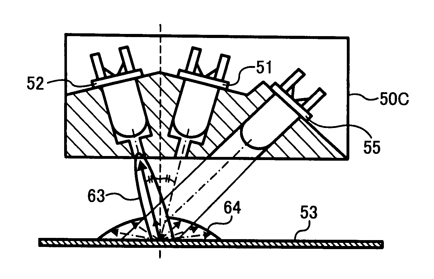
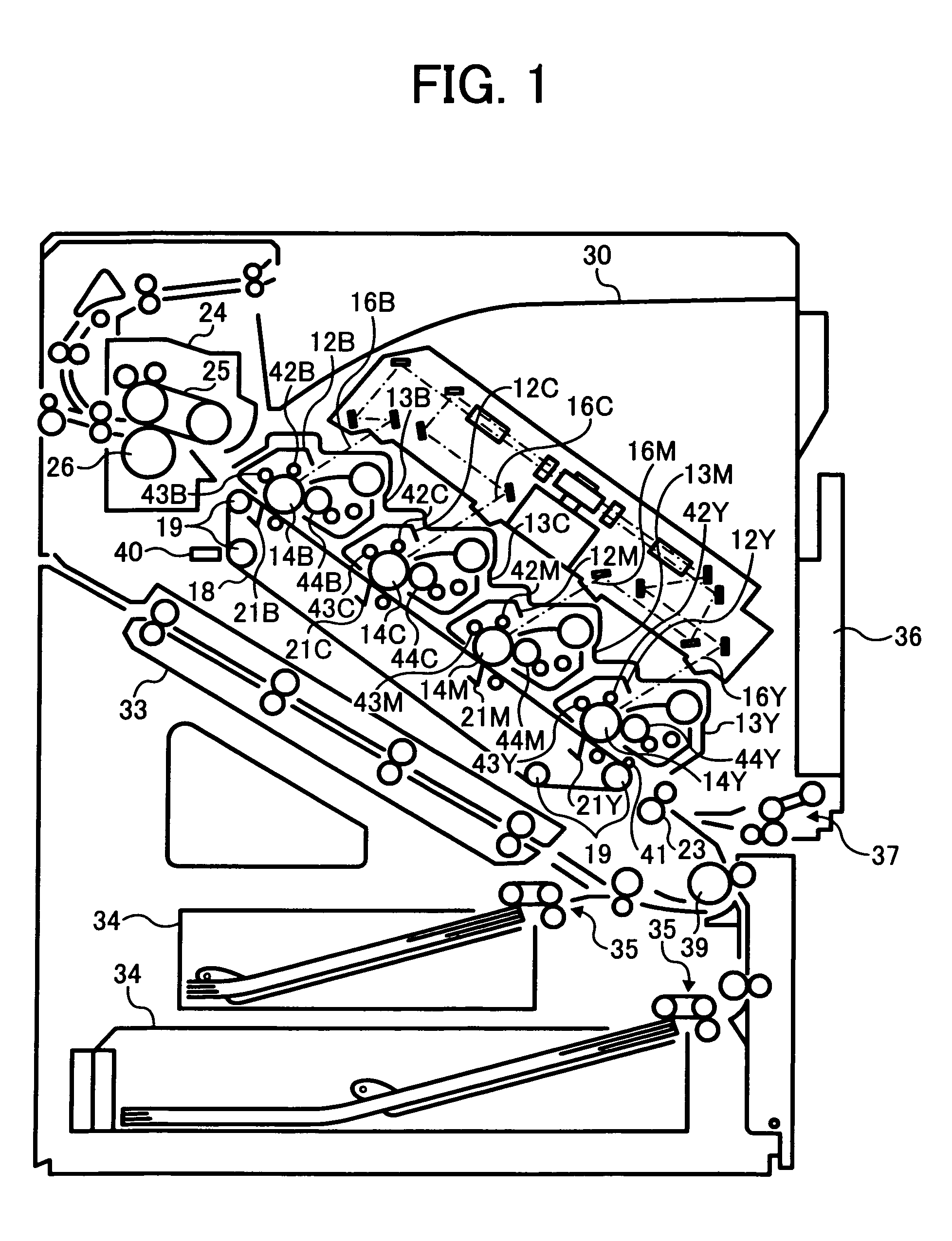
[0102] Having described the present disclosure in general, several preferred embodiments of the method of converting the amount of toner adhesion will be described herein below according to the present invention in reference to FIGS. 1 through 35.

[0103] In the first place, before detailing the configuration and the function in this embodiment, the circumstances for realizing the present invention will be described.

[Examination on Configuration and Function of Optical Detection Means]

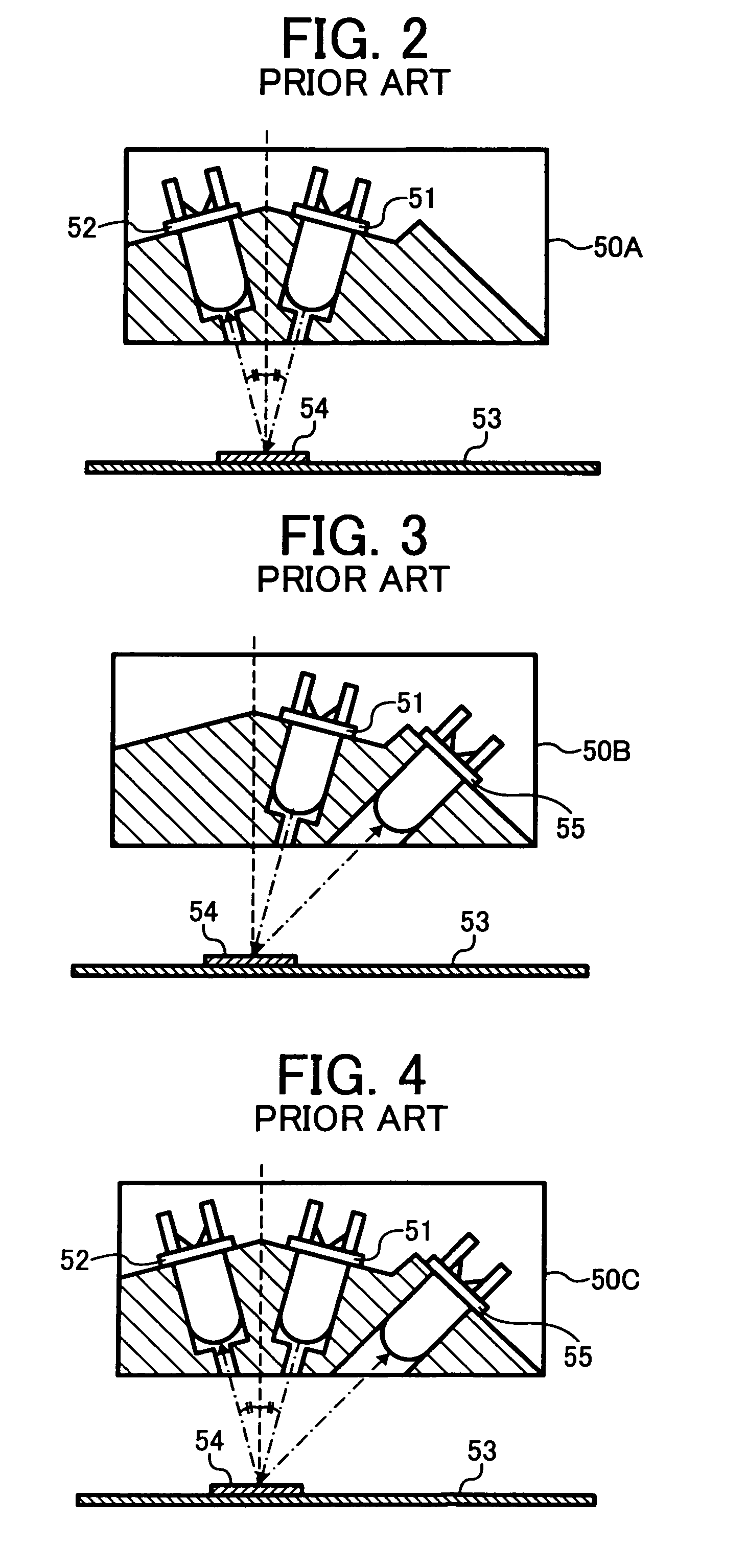
[0104] When it is considered which type of optical sensors is used for detecting the density gradation pattern on the transfer belt serving as the target face for detection,

[0105] (A) in a first type of the sensor configured to detect only the regular reflection light, there is a drawback in that the detection up to the high adhesion range is ...


PUM


Abstract

An image forming method and apparatus capable of implementing accurately and constantly an improved conversion of the amount of toner adhesion over the entire range of the amount of adhesion. The method includes the steps of computing a normalization value as a relative output ratio of the regular reflection output to a background regular reflection component from the surface extracted from the regular reflection light, in which the regular reflection output is obtained by detecting a plurality of gradation toner patterns with a sensor configured to simultaneously detect regular reflection light and diffuse reflection light; obtaining a diffuse reflection output conversion factor by either (1) subtracting the normalization value multiplied by the diffuse reflection output voltage generated by the surface from the diffuse reflection output voltage, or (2) subtracting the normalization value multiplied by a diffuse reflection output voltage increment, which is computed as the difference between the diffuse reflection output voltage and another diffuse reflection output voltage obtained when a light emitting device is turned off, from the diffuse reflection output voltage increment; and subjecting the relation between the diffuse reflection output conversion factor and the amount of adhesion to a polynomial approximation.

Description

[0001] This application claims priority to Japanese Patent Application No. 2005-193026, filed with the Japanese Patent Office on Jun. 30, 2005, the entire contents of which are hereby incorporated by reference. FIELD OF INVENTION [0002] The invention generally relates to image forming methods and apparatuses, and more specifically to an image forming method and apparatus capable of implementing improved conversion of the amount of toner or particle adhesion useful for achieving stable image density control in full-color electrophotographic image forming apparatus such as a copying machine and a laser beam printer among others. BACKGROUND OF INVENTION [0003] In order to implement a stable image density constantly in electrophotographic image forming apparatuses, a toner patch (or, gradation pattern) for detecting the image density is formed conventionally on an image bearing member such as a photoreceptor, for example. The density of the gradation pattern is detected with an optical ...

Claims


Application Information

Patent Timeline
Patent Type & Authority Applications(United States)
IPC IPC(8): G03G15/00
CPCG03G2215/00042G03G15/5058G03G2215/0119G03G2215/00059
Inventor WATANABE, NAOTOHASEGAWA, SHINKAMAJI, HIDEKIKATO, SHINJIISHIBASHI, HITOSHIFUJIMORI, KOHTATANAKA, KAYOKOHIRAYAMA, YUUSHIENAMI, TAKASHIKOBAYASHI, SHINJIKOBAYASHI, KAZUMIUCHIDA, FUKUTOSHISAWAYAMA, NOBORU
Owner RICOH KK
Why Eureka
Try Eureka