DC converter with halt mode setting means

a halt mode and converter technology, applied in the direction of process and machine control, ignition automatic control, instruments, etc., can solve the problems of reducing the size of semiconductor elements, preventing the occurrence of over-current, and reducing the size of circuits. , to achieve the effect of reducing or eliminating many, preventing the occurrence of over-current, and reducing the size of circuits

Inactive Publication Date: 2006-01-05
RICOH ELECTRONIC DEVICES CO LTD
View PDF3 Cites 0 Cited by
  • Summary
  • Abstract
  • Description
  • Claims
  • Application Information

AI Technical Summary

Benefits of technology

[0019] Accordingly, an exemplary embodiment of the invention provides a DC converter with a halt mode setting for preventing the occurrence of over-current while alleviating the increase in the size of circuits. Also, an exemplary method for setting up such halt mode is also disclosed, having most, if not all, of the advantages and features of similar employed apparatuses and methods, while reducing or eliminating many of the aforementioned disadvantages.

Problems solved by technology

However, since the transistors used as the semiconductor switch 1 are typically of a low-current (i.e., slow response) type, the circuit is particularly susceptible to over-current conditions.
However, since the transistors in the current limiter 300 are of a low current consuming type, or slow responding type, when the semiconductor switches to reduce the normal current consumption, the occurrence of the over-current remains a problem.
In addition, if the current limiter 300 is formed with semiconductor switches having the driving capability suitable for responding to the switching, the increase in size of the semiconductor elements will not be as great.
This measure, however, may result in undue increase in current consumption as well as production costs.

Method used


Image

  • DC converter with halt mode setting means
  • DC converter with halt mode setting means
  • DC converter with halt mode setting means

Examples


Embodiment Construction

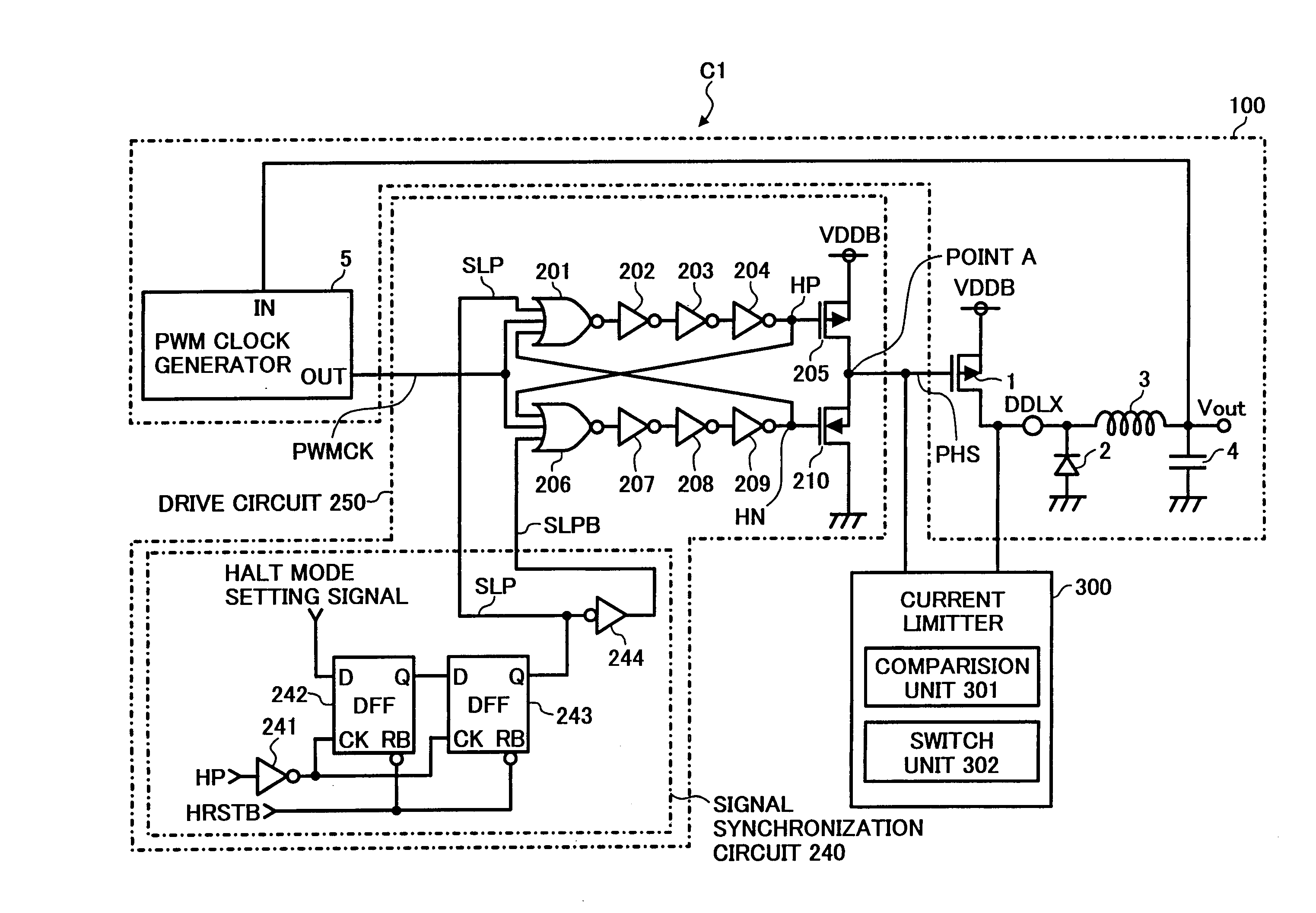
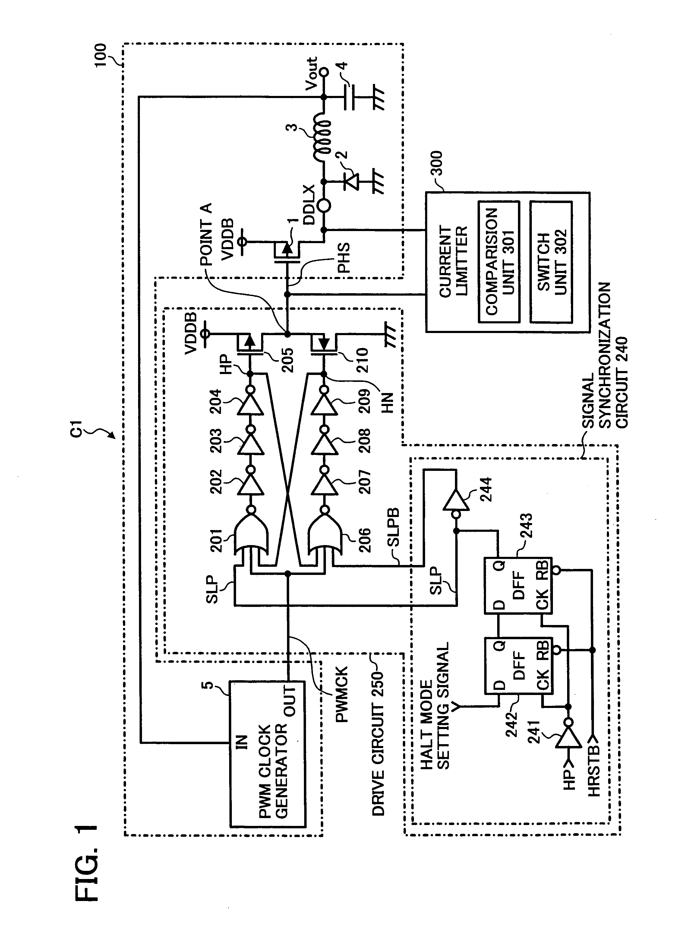
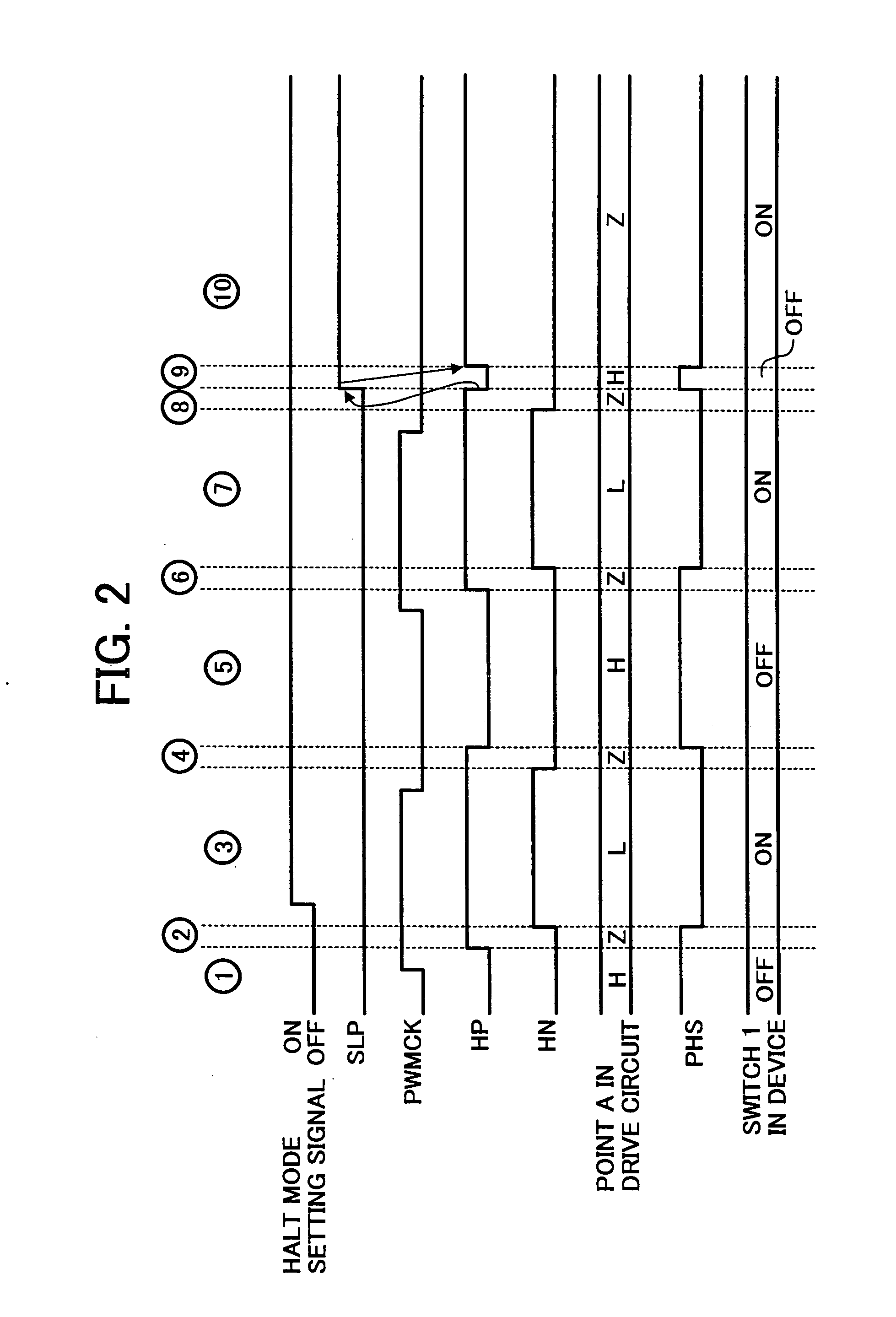
[0021] A DC converter according to an exemplary embodiment includes a semiconductor switch, and a clock generator for outputting a clock signal to a gate of the semiconductor switch to be utilized for controlling an on / off time of the semiconductor switch such that a predetermined power is output from the generator. The DC converter further includes a drive circuit for switching the semiconductor switch into the continuous-on state according to a halt mode setting requirement regardless of the clock signal when the semiconductor switch normally repeating on / off operations in response to the clock signal is in its off-state.

[0022] The drive circuit may further include a signal synchronization unit for switching the semiconductor switch into the continuous-on state according to the halt mode setting requirement after the semiconductor switch is turned off in response to the clock signal input from the clock generator.

[0023] In addition, the drive circuit may further include an off-...


PUM


Abstract

A DC converter with a halt mode setting is disclosed for preventing the occurrence of over-current while alleviating the increase in the size of circuits, along with a method for setting up such a halt mode. The DC converter includes a semiconductor switch, a clock generator for outputting a clock signal to a gate of the semiconductor switch to be utilized for controlling an on / off time of the semiconductor switch such that a predetermined power is output from the generator, and a drive circuit for switching the semiconductor switch to the continuous-on state according to a halt mode setting requirement regardless of the clock signal, when the semiconductor switch, normally repeating on / off operations responsive to the clock signal, is in its off-state.

Description

FIELD OF THE INVENTION [0001] The invention generally relates to DC converters having a halt mode setting operation for preventing the occurrence of over-current while minimizing the size of circuits. A related method for setting up halt modes is also disclosed. [0002] This document claims priority to Japanese Patent Application No. 2002-261234, filed with the Japanese Patent Office on Sep. 6, 2002, the entire contents of which are hereby incorporated by reference. BACKGROUND OF THE INVENTION [0003] Power circuits have been used in various electronic circuits to convert incoming electrical signals to a desired voltage type (e.g., alternating current (AC), direct current (DC), etc.). Circuits capable of converting signals into DC by controlling on / off-time of semiconductor switches are increasingly becoming more important. These circuits can be brought to a halt (or dormant) mode when the operation mode of a controlling CPU (which implements power feeding) is switched to a low curren...

Claims


Application Information

Patent Timeline
Patent Type & Authority Applications(United States)
IPC IPC(8): G05F1/40H02M3/155H02M3/156
CPCH02M1/32Y02B70/16H02M2001/0032H02M3/156H02M1/0032Y02B70/10
Inventor MANABE, KATSUHIKOKATOH, TOMONARISUGIYAMA, MINORUMATSUSHIMA, MAKOTOUEDA, TADAYOSHI
Owner RICOH ELECTRONIC DEVICES CO LTD
Why Eureka
Try Eureka