Charging unit and image forming apparatus incorporating the unit

a charging unit and image forming technology, applied in the direction of corona discharge, stoves or ranges, instruments, etc., can solve the problems of inordinate maintenance of charging wires, arcing, and high voltages that require special insulation, and achieve the effect of reducing or eliminating

Inactive Publication Date: 2008-03-04
RICOH KK
View PDF27 Cites 8 Cited by
  • Summary
  • Abstract
  • Description
  • Claims
  • Application Information

AI Technical Summary

Benefits of technology

[0034]Accordingly, an exemplary embodiment of the invention provides a charging unit and an image forming apparatus incorporating the charging unit, having most, if not all, of the advantages and features of similar employed units and materials, while reducing or eliminating many of the aforementioned disadvantages.
[0053]The image bearing member suitable in use in the invention may comprise an organic photoconductor. A protective layer is disposed as an uppermost layer overlying the photosensitive layer, containing metal oxide particles for protecting the photoreceptor image bearing member by improving durability. In addition, lubricant particles of fluorocarbon resin, for example, can be dispersed in the protective layer to improve the lubricating properties of the surface of image bearing member.
[0055]Alternatively, the charging unit including the charging roller and image bearing member may form in advance an integral structure, a process cartridge, to subsequently be incorporated into the printer. This process cartridge can be handled conveniently as a single unit detachably with respect to the casing main body of the full-color printer.

Problems solved by technology

Several problems have been associated with corona generating devices.
For example, the use of very high voltages requires special insulation, inordinate maintenance of charging wires, and generates arcing caused by non-uniformities, and the contamination of corona wires.
More importantly, it generates ozone and oxides of nitrogen, which eventually results in an adverse effect on the quality of the final output print produced by the reproduction apparatus.
The contact charging devices, however, have several difficulties such as, for example, contamination by toner particles electrostatically adsorbed onto image bearing member (photoreceptor) and concomitant uneven charging, thereby resulting in an adverse effect on the life of charging unit.
However, there exists an upper limit for the width of the gap between charging roller and photoreceptor (which is hereinafter referred to as “charging gap”) primarily due to the properties of materials for forming the charging roller.
Then, if the charging gap is larger exceeding a certain tolerance, abnormal discharge takes place and uneven image density emerges in the images produced.
In addition, since the proper value of charging bias varies depending on the charging gap, undesirable situation arises even in the case where the charging gap is within the certain tolerance: if a large deviation exits in the charging gap, the charging bias cannot be large enough to retain a suitable charging voltage where the charging gap is large, while discharge energy may be too large at the location where the charging gap is small.
As a result, the charging potential decreases due to the deficient charging bias for the former case, while filming of toner and additives onto photoreceptor and / or the increase in photoreceptor abrasion take place for the latter case due to the excessive discharge energy.
For example, in the case when the charging member is formed of rubber, the member suffers from a relatively large change in hardness and this result in a large change in charging gap.
In spite of the abovementioned disclosures, various difficulties remain yet to be solved.
However, almost none has been found on the margin of fluctuation during the rotation of charging roller and photoreceptor, and the charging gap deviation in the longitudinal direction of the photoreceptor.
In the case when the charging member is formed of rubber, the difficulty persists in accuracy of cutting work of the rubber material and in relatively large change in hardness with temperature.
It has drawbacks due to the hardness, however, such as abrasion over the period of time when the resinous material is used as a thin film to form the gap forming member, and / or filtering out of adhesive agent from the edge portions and concomitant toner adhesion thereto.
When the photoreceptor formed of organic photoconductors, some damages may take place at the locations to which the charging forming member is brought into contact.
Although some improvement of durability is expected by the use of the thick gap forming member, there persists a difficulty of relatively large thickness and concomitant increase in deviation of the charging gap.
However, a further gap between the charging layer and the gap forming member has to be provided to prevent the leakage there between.
This may result in an undue increase in the length of core shaft of the charging roller and the size of the image forming apparatus as a whole.
This may necessitate complex and costly mechanisms for measurements and adjustments.

Method used


Image

  • Charging unit and image forming apparatus incorporating the unit
  • Charging unit and image forming apparatus incorporating the unit
  • Charging unit and image forming apparatus incorporating the unit

Examples


example 1

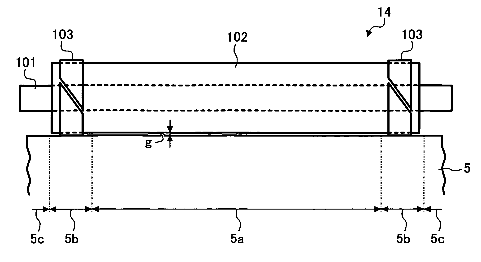
[0268]A plurality of charging rollers, A through F, were formed according to the there embodiments described above, and subsequently subjected to several measurements and observations such as charging gaps, the hardness of the charging roller, contamination on the roller, and defects on the photoreceptor, after the running test.

(Charging Roller A)

[0269]A charging layer was formed over the surface area of a stainless steel core shaft having an 8-mm-diameter, by injection molding a resin composition, which contains 60 parts by weight of ion-conductive agent consisting of polyolefin polymer with quaternary ammonium salt in 100 parts by weight of ABS resin, to find a volume resistance of 106 Ω cm for the resultant charging layer.

[0270]Gap holding members, which were formed of 45-μm-thick polyethylene terephthalate sheets with 8-mm-width each provided with 15-μm-thick adhesive layer adhered thereto, were then affixed onto both ends of the charging layer, whereby a charging roller A was f...

example 2

[0417]A running test was carried out for the combination of the photoreceptor 5 and the charging roller 14 formed as abovementioned eighth embodiment, which was provided with gap holding members 14c formed of polyethylene fixed to both ends of the charging member 14b.

[0418]Although abnormal images having light or dark spots were found under insufficient AC charging bias conditions, this difficulty was obviated by setting the AC charging bias Vp-p as 2.1 kV to result in images of uniform density. Therefore, the running test was performed at the 2.1 kV bias.

[0419]After outputting 20,000 copies, no abnormality was recognized on the output images and outward appearance of photoreceptor. In addition, the charging roller 14 by itself had no appreciable contamination even though few toner particles were found on the cleaning brush.

example 3

[0420]Another running test was carried out for the combination of the photoreceptor 5 and the charging roller 14 formed as abovementioned tenth embodiment, which was provided with the step portions each groove-shaped at the both ends of the structure fit by heat shrinking PFA tube.

[0421]Although abnormal images having light or dark spots were found under insufficient AC charging bias conditions, this difficulty was obviated by setting the AC charging bias Vp-p as 2.2 kV to result in images of uniform density. The running test was therefore performed at the 2.2 kV bias.

[0422]After outputting 20,000 copies, no abnormality was recognized on the output images and outward appearance of photoreceptor. In addition, the charging roller 14 had no appreciable contamination even though few toner particles were found on the cleaning brush.


PUM


Abstract

A charging unit is disclosed capable of reducing undue variation and fluctuation margin of a charging gap, and controlling accurately the proper gap durably over the change of environmental conditions, which is suitably incorporated into an image forming apparatus. The charging unit is configured to charge an image bearing member in a non-contact arrangement, including a charging roller provided with a core shaft, a charging member formed of electroconductive resin integrally disposed on the periphery of the core shaft, and gap holding members formed of insulating resin each disposed at respective ends of the charging member outside an image forming region. The control of the charging gap is feasible by either forming the gap with a charging member having such a materials condition as to satisfy the relation, |G30−G10|×5<G20, where G10, G20 and G30 are the gap averages at 10°, 20° and 30° C., respectively; or providing the charging roller with gears mounted on respective ends to be engaged with further gears mounted on flanges of the image bearing member to be driven along the rotation, and forming these gears such that the least common multiple of numbers, Nc and Np, is Nc×Np, where Nc and Np are the numbers of gear teeth for the charging roller and image bearing member, respectively.

Description

CROSS REFERENCE TO RELATED APPLICATIONS[0001]This application claims priority to Japanese applications No. 2004-004318 and 2004-296877, filed on Jan. 9, 2004 and Oct. 8, 2004, respectively, the disclosure of which is incorporated by reference herein in its entirety.BACKGROUND OF THE INVENTION[0002]1. Field of the Invention[0003]The invention relates generally to charging units and image forming apparatuses incorporating the units, and more specifically to a charging unit configured to reduce fluctuations of a charging gap, caused by the change in environmental conditions, a process cartridge, and an image forming apparatus incorporating the charging unit.[0004]2. Discussion of the Background[0005]The process of electrophotographic image formation is well known and is useful for both analog and digital copying and other reproduction techniques. Generally, the electrophotographic reproduction process is initiated by performing substantially uniform charging onto an image bearing membe...

Claims


Application Information

Patent Timeline
Patent Type & Authority Patents(United States)
IPC IPC(8): G03G15/02G03G21/18G03G21/20
CPCG03G21/20G03G15/025G03G2215/021G03G2221/1693F24C15/086F24C3/14
Inventor KOSUGE, AKIO
Owner RICOH KK
Why Eureka
Try Eureka