
Charging unit and image forming apparatus incorporating the unit
a charging unit and image forming technology, applied in the direction of corona discharge, stoves or ranges, instruments, etc., can solve the problems of inordinate maintenance of charging wires, arcing, and high voltages that require special insulation, and achieve the effect of reducing or eliminating
- Summary
- Abstract
- Description
- Claims
- Application Information
AI Technical Summary
Benefits of technology
Problems solved by technology
Method used
Image

Examples
example 1
[0266] A plurality of charging rollers, A through F, were formed according to the there embodiments described above, and subsequently subjected to several measurements and observations such as charging gaps, the hardness of the charging roller, contamination on the roller, and defects on the photoreceptor, after the running test.
(Charging Roller A)
[0267] A charging layer was formed over the surface area of a stainless steel core shaft having an 8-mm-diameter, by injection molding a resin composition, which contains 60 parts by weight of ion-conductive agent consisting of polyolefin polymer with quaternary ammonium salt in 100 parts by weight of ABS resin, to find a volume resistance of 106 Ω cm for the resultant charging layer.
[0268] Gap holding members, which were formed of 45-μm-thick polyethylene terephthalate sheets with 8-mm-width each provided with 15-μm-thick adhesive layer adhered thereto, were then affixed onto both ends of the charging layer, whereby a charging roller ...
example 2
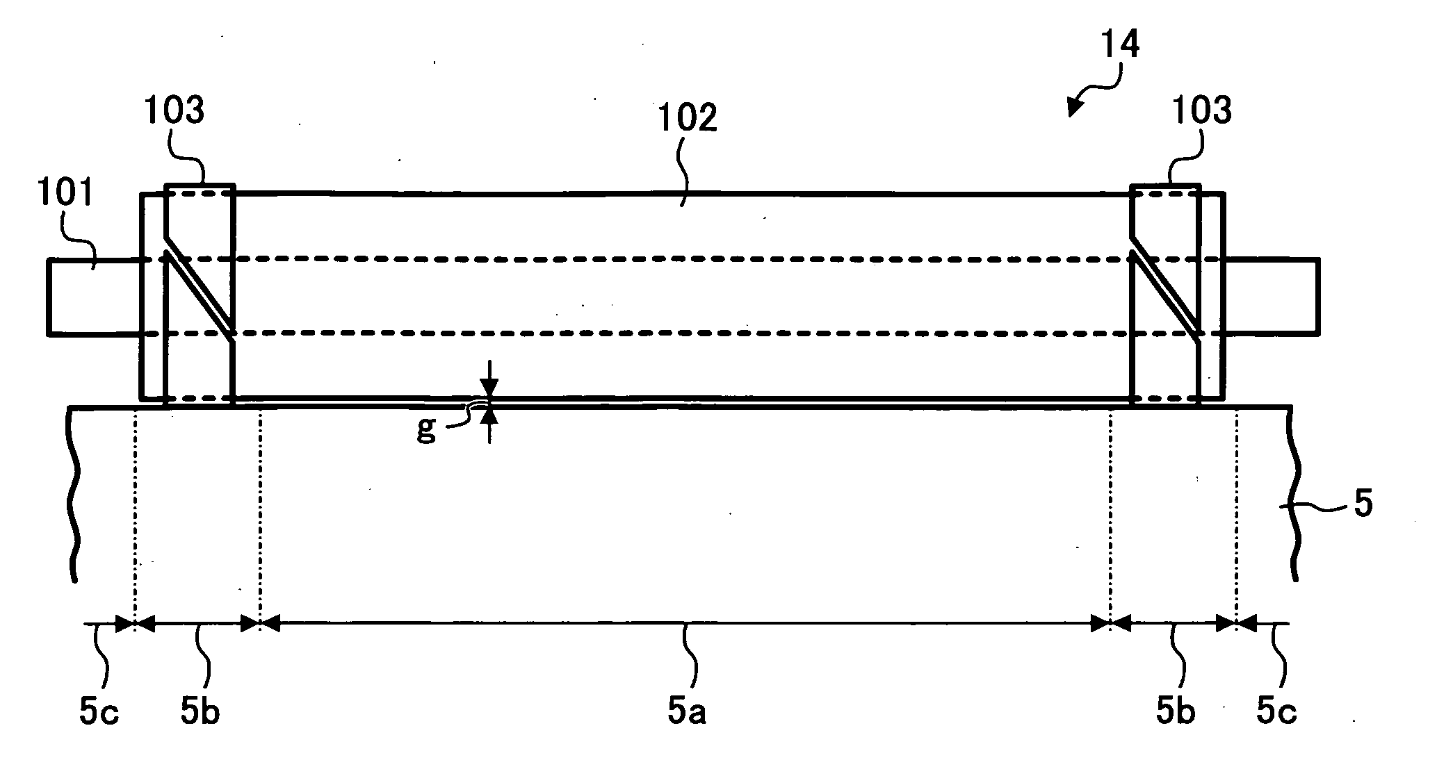
[0411] A running test was carried out for the combination of the photoreceptor 5 and the charging roller 14 formed as abovementioned eighth embodiment, which was provided with gap holding members 14c formed of polyethylene fixed to both ends of the charging member 14b.
[0412] Although abnormal images having light or dark spots were found under insufficient AC charging bias conditions, this difficulty was obviated by setting the AC charging bias Vp-p as 2.1 kV to result in images of uniform density. Therefore, the running test was performed at the 2.1 kV bias.
[0413] After outputting 20,000 copies, no abnormality was recognized on the output images and outward appearance of photoreceptor. In addition, the charging roller 14 by itself had no appreciable contamination even though few toner particles were found on the cleaning brush.
example 3
[0414] Another running test was carried out for the combination of the photoreceptor 5 and the charging roller 14 formed as abovementioned tenth embodiment, which was provided with the step portions each groove-shaped at the both ends of the structure fit by heat shrinking PFA tube.
[0415] Although abnormal images having light or dark spots were found under insufficient AC charging bias conditions, this difficulty was obviated by setting the AC charging bias Vp-p as 2.2 kV to result in images of uniform density. The running test was therefore performed at the 2.2 kV bias.
[0416] After outputting 20,000 copies, no abnormality was recognized on the output images and outward appearance of photoreceptor. In addition, the charging roller 14 had no appreciable contamination even though few toner particles were found on the cleaning brush.
PUM
 Abstract
Description
Claims
Application Information