Direction control valve

a direction control valve and direction technology, applied in mechanical equipment, suspensions, transportation and packaging, etc., can solve the problems of increasing the energy loss of hydraulic oil and the increase of hydraulic oil energy loss, so as to reduce the energy loss of hydraulic fluid produced when the port communicates with the communication object port, the effect of reducing the energy loss of hydraulic fluid

Inactive Publication Date: 2007-02-01
DENSO CORP +1
View PDF11 Cites 8 Cited by
  • Summary
  • Abstract
  • Description
  • Claims
  • Application Information

AI Technical Summary

Benefits of technology

[0013] Thus, a period in which both of the first and second communication switching ports communicate with the communication object port can be reduced when the port communicating with the communication object port is switched betwe

Problems solved by technology

In consequence, the hydraulic oil supplied to the high-pressure communication switching port 110b flows into the low-pressure communication sw

Method used


Image

  • Direction control valve
  • Direction control valve
  • Direction control valve

Examples


Embodiment Construction

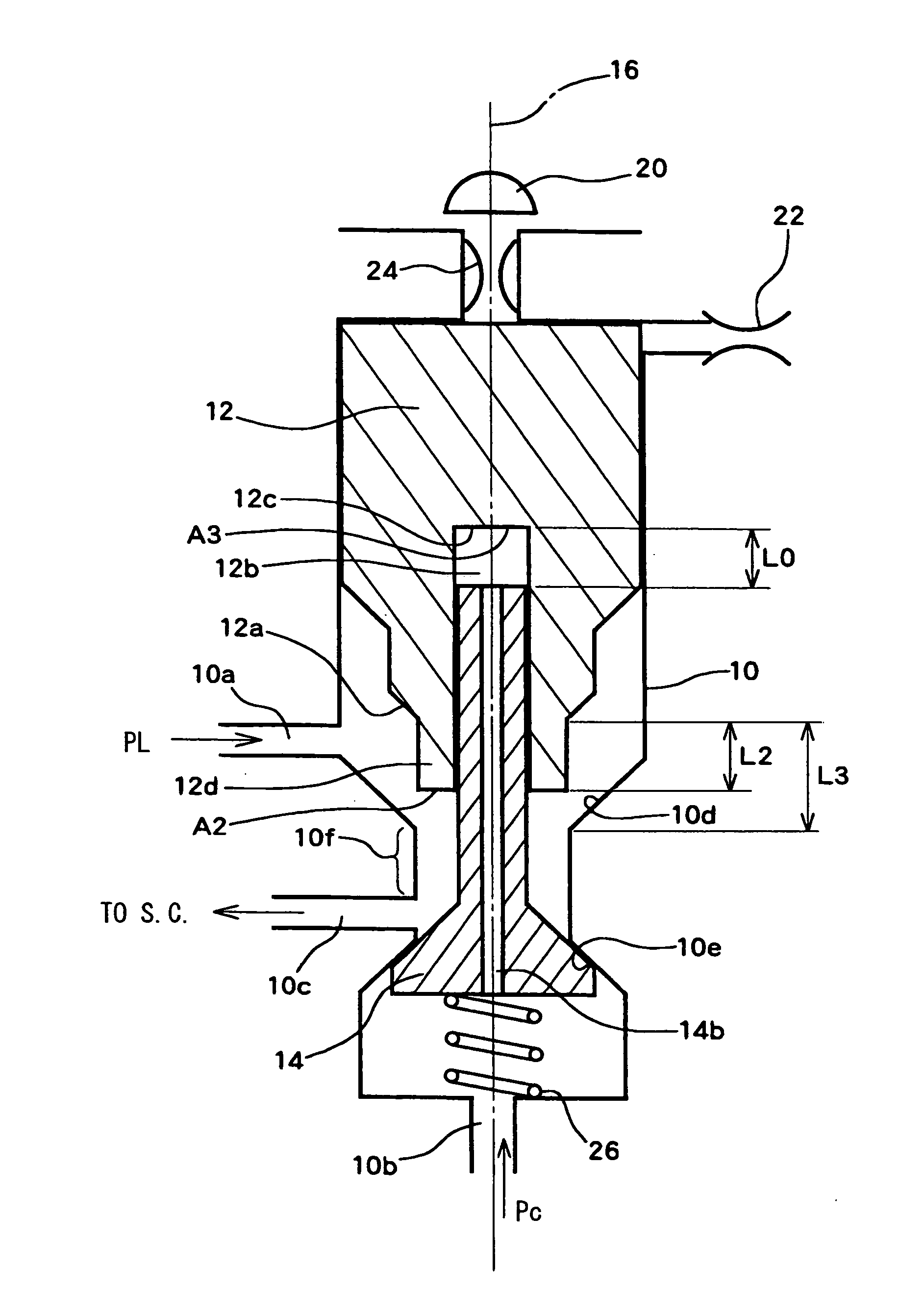
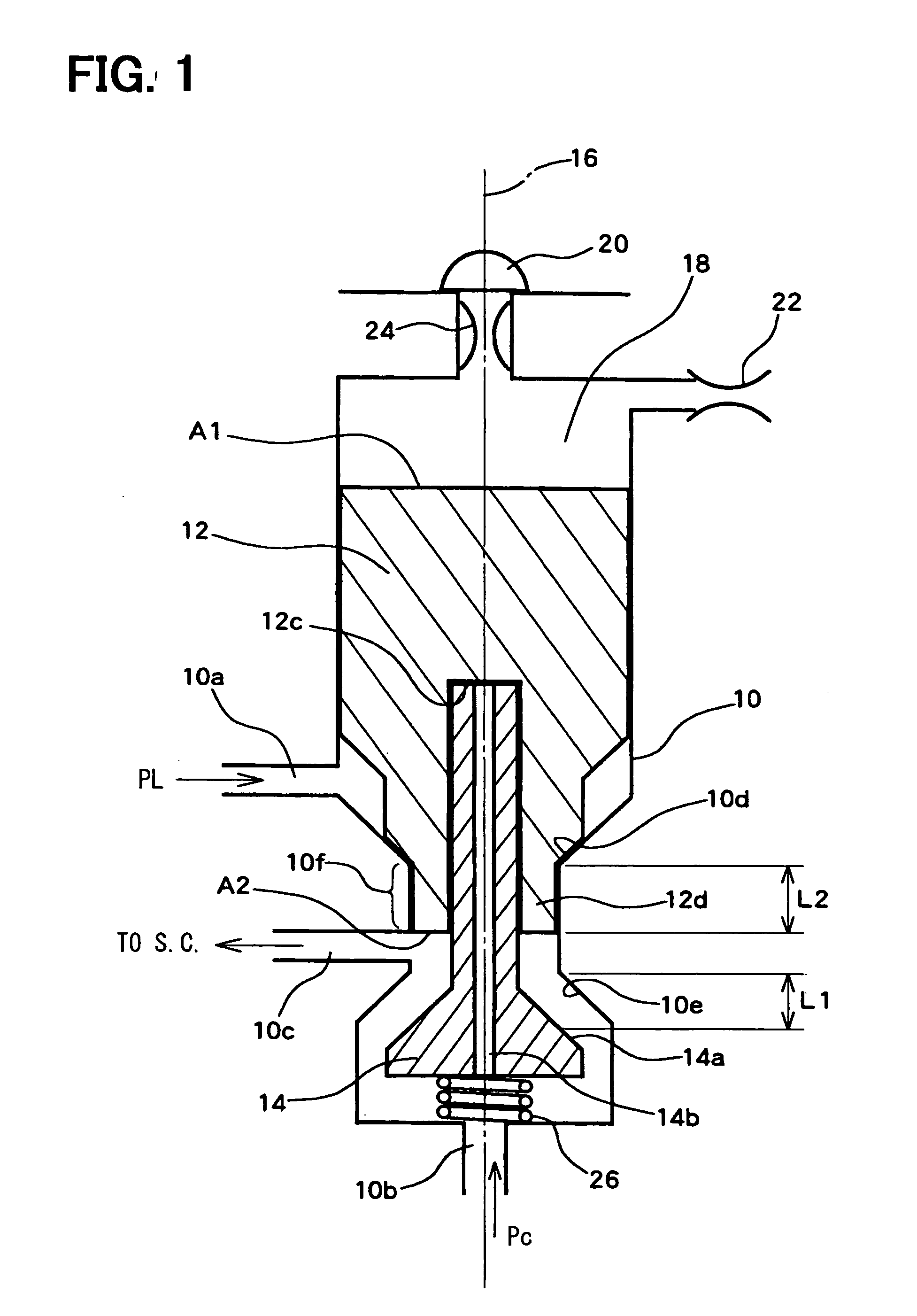
[0032] Referring to FIG. 1, a direction control valve according to an example embodiment of the present invention is illustrated. The direction control valve according to the present embodiment has a valve body 10, a first movable member 12 and a second movable member 14. The valve body 10 is formed with a first communication switching port 10a, a second communication switching port 10b, and a communication object port 10c. Hydraulic fluid pressure PL is supplied to the communication switching port 10a, and hydraulic fluid pressure Pc is supplied to the second communication switching port 10b. The communication object port 10c is connected to a switch chamber (S.C., not shown). The pressure Pc supplied to the communication switching port 10b is set higher than the pressure PL supplied to the communication switching port 10a. The hydraulic fluid is an incompressible fluid. For example, hydraulic oil or fuel for an internal combustion engine may be used as the hydraulic fluid.

[0033] ...


PUM


Abstract

In a direction control valve, a bottom face of an insertion hole of a first movable member is at a predetermined distance from a second movable member with respect to a first axial direction when communication between a first communication switching port and a communication object port is made and communication between a second communication switching port and the communication object port is broken. The bottom face contacts and pushes the second movable member in a second axial direction opposite to the first axial direction after the first movable member moves in the second axial direction by the predetermined distance while the first and second movable members move in the second axial direction to switch a port communicating with the communication object port from the first communication switching port to the second communication switching port.

Description

CROSS REFERENCE TO RELATED APPLICATION [0001] This application is based on and incorporates herein by reference Japanese Patent Application No. 2005-222162 filed on Jul. 29, 2005. BACKGROUND OF THE INVENTION [0002] 1. Field of the Invention [0003] The present invention relates to a direction control valve, and more particularly to a direction control valve equipped with a valve body, which is formed with first and second communication switching ports and a communication object port, and a movable member axially moving inside the valve body to switch a port communicating with the communication object port between the first communication switching port and the second communication switching port. [0004] 2. Description of Related Art [0005]FIG. 13 illustrates an example structure of this type of direction control valve. The direction control valve shown in FIG. 13 is a three-way valve having a valve body 110 and a movable member 112. The valve body 110 is formed with communication swit...

Claims


Application Information

Patent Timeline
IPC IPC(8): F15B13/04
CPCF16K11/048Y10T137/86686Y10T137/86919Y10T137/87225
Inventor YAMAMOTO, YOSHIHISATOMITA, HIROKUNIHOTTA, YOSHIHIROWAKISAKA, YOSHIFUMIKAWAMURA, KIYOMI
Owner DENSO CORP
Why Eureka
Try Eureka