Insertion instrument for non-linear medical devices

a non-linear, medical device technology, applied in the direction of eye surgery, eye treatment, stents, etc., can solve the problems of difficult overall handling, unsatisfactory types of cap designs, and difficult process of insertion of small medical devices into eye portions, etc., to avoid contact, and avoid mechanically disrupting or damaging tissue

Inactive Publication Date: 2007-02-01
SURMODICS INC
View PDF35 Cites 68 Cited by
  • Summary
  • Abstract
  • Description
  • Claims
  • Application Information

AI Technical Summary

Benefits of technology

[0018] When in an engaged position, the securing member of the insertion tool can fasten the head of the insertable medical device. In an engaged position, the distal end of the securing member generally does not extend beyond the distal end of the head of the insertable medical device. This minimizes or eliminates contact between the distal end of the insertion instrument and tissue of the target site and therefore avoids mechanically disrupting or damaging tissue, such as the conjunctival or scleral tissues of the eye. The securing member is designed to be compact and unobtrusive, but can also sufficiently stabilize a device in a manner so that most of, or the entire portion of the device that is not in contact with the securing member can be rotatably inserted into a target site.
[0019] The inventive design and function of the insertion instrument provides the needed stability for processes involving the rotational insertion of smaller insertable medical devices. For example, given the more delicate environment of the target tissue such as the eye, the invention provides an insertion tool that is designed to allow the user to stably hold the medical device during insertion into the target site, and when actuated, to gently release the device in a manner that does not disrupt its placement in the tissue of the target site.
[0020] Another advantageous feature of the insertion instrument is a distal portion that has a configuration that allows favorable viewing of the target site, including the medical device that is engaged by the securing member. In many aspects the distal portion of the instrument is small...

Problems solved by technology

The process of inserting these types of small medical devices into portions of the body such as the eye, however, can be rather delicate.
This process can require gentle techniques, as the scleral tissue is soft and can be disrupted or damaged by mechanically aggressive or crude techniques.
Furthermore, overall handling can be challenging due to the relatively small size of the insertable device.
While these rounded edges can be beneficial with regard to patient comfort, etc., these types of cap designs are not ideal for the process of insertion of the medical device.
Cap configurations tha...

Method used


Image

  • Insertion instrument for non-linear medical devices
  • Insertion instrument for non-linear medical devices
  • Insertion instrument for non-linear medical devices

Examples


Embodiment Construction

[0037] The embodiments of the present invention described below are not intended to be exhaustive or to limit the invention to the precise forms disclosed in the following detailed description. Rather, the embodiments are chosen and described so that others skilled in the art can appreciate and understand the principles and practices of the present invention. All publications and patents mentioned herein are hereby incorporated by reference. The publications and patents disclosed herein are provided solely for their disclosure. Nothing herein is to be construed as an admission that the inventors are not entitled to antedate any publication and / or patent, including any publication and / or patent cited herein.

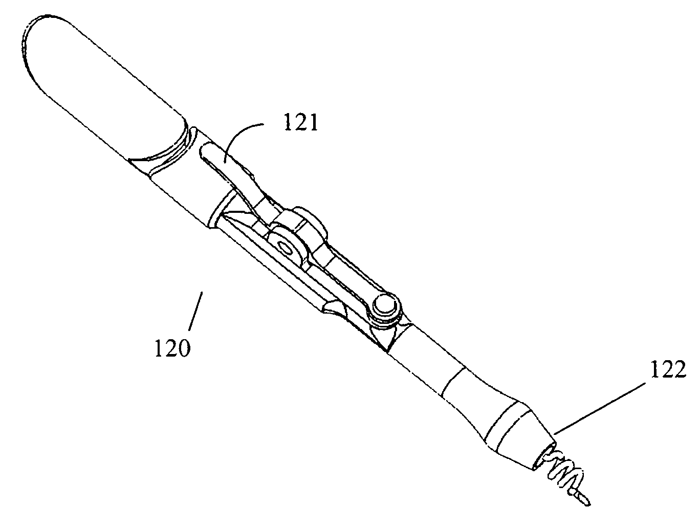
[0038] An “insertion instrument” or “instrument” as used herein refers to a tool used to rotatably insert an implatable medical device into a target site in a subject. An “insertable medical device” or “device” refers to a medical article that can be held by the insertion instrum...


PUM


Abstract

The invention provides an insertion instrument and methods for rotatably inserting an insertable medical device into a target region of the body. In particular, the instrument can be used in a method for rotatably inserting a medical device having a helical shape into a portion of the eye. The instrument includes a distal portion with a securing member that can hold a portion of the device during the rotational insertion process, and an actuating member that can be triggered to gently release the device upon insertion of the device into the target site.

Description

CROSS-REFERENCE TO RELATED APPLICATION [0001] The present non-provisional Application claims the benefit of commonly owned provisional U.S. patent application having Ser. No. 60 / 682,454, filed on May 18, 2005, and entitled Insertion Instrument for Non-Linear Medical Devices.FIELD OF THE INVENTION [0002] The invention relates to an instrument and methods for inserting a non-linear medical device into a limited-access region of the body. More specifically, the invention relates to a device and methods for inserting a non-linear drug-delivery device into the vitreous of the eye. BACKGROUND OF THE INVENTION [0003] Tools for inserting linear-type medical devices such stents and grafts into the vasculature are well known in the art. Stent insertion has been traditionally performed by crimping a stent onto the insertion element such as catheter, then transporting the stent via the vasculature to a target site. More recently, improvements in this procedure have been seen in stent insertion ...

Claims


Application Information

Patent Timeline
IPC IPC(8): A61F9/00
CPCA61F2/88A61F9/007A61F9/0017A61F9/00
Inventor VARNER, SIGNE E.MCCORMICK, MATTHEWBARNES, AARON C.KLOKE, TIMOTHY M.FOX BEELEY, NATHAN ROBERTPATTON, DOUG
Owner SURMODICS INC
Why Eureka
Try Eureka