An Electromechanical Generator for Converting Mechanical Vibrational Energy into Electrical Energy

a technology of electrical energy and mechanical vibration, which is applied in the direction of dynamo-electric components, dynamo-electric circuits, dynamo-electric machines, etc., can solve the problems of increasing manufacturing difficulty, excessive vibration of mass, and inability to precisely manufacture components, etc., to achieve easy manufacturing, low cost, and limit excessive vibration

Active Publication Date: 2021-04-01
PERPETUUM +1
View PDF0 Cites 0 Cited by
  • Summary
  • Abstract
  • Description
  • Claims
  • Application Information

AI Technical Summary

Benefits of technology

[0013]The present invention is predicated on the finding that a flat annular spring can be employed as a resilient device to limit excessive vibration. The flat annular spring can be readily manufactured with low cost and low complexity to provide a flat spring with highly accurate constant thickness. By employing a flat annular spring as a resilient device, a hard-face hearing element, and another compliant component, are not required. Sliding motion between the resilient device and any other component can be avoided or at least minimised, which eliminates or minimizes contact wear.

Problems solved by technology

The electromechanical generator may, in use, be subjected to a large shock force or vibration that causes the sprung mass to vibrate with excessively large amplitude, with result that the mass may physically impact upon the outer casing of the device, or other components, at the limit of travel of the sprung mass.
However, the added complexity of frustoconical springs increases the difficulty of manufacture.
However, in the case of an energy harvester, the size of the in-service forces means that the joints must be especially secure, and so precision assembly of imprecise components is therefore largely impractical in this instance.
The known frustoconical springs disclosed in WO-A-2014 / 076143 are complex to manufacture accurately and to use in service.
Any adjustment of springs after forming is complicated by their inherent compliance.
However, there is a problem in providing a spring design which can achieve improved performance as compared to the known use of frustoconical springs, and is still easy to manufacture and incorporate into an accurate energy harvester design.

Method used


Image

  • An Electromechanical Generator for Converting Mechanical Vibrational Energy into Electrical Energy
  • An Electromechanical Generator for Converting Mechanical Vibrational Energy into Electrical Energy
  • An Electromechanical Generator for Converting Mechanical Vibrational Energy into Electrical Energy

Examples


Embodiment Construction

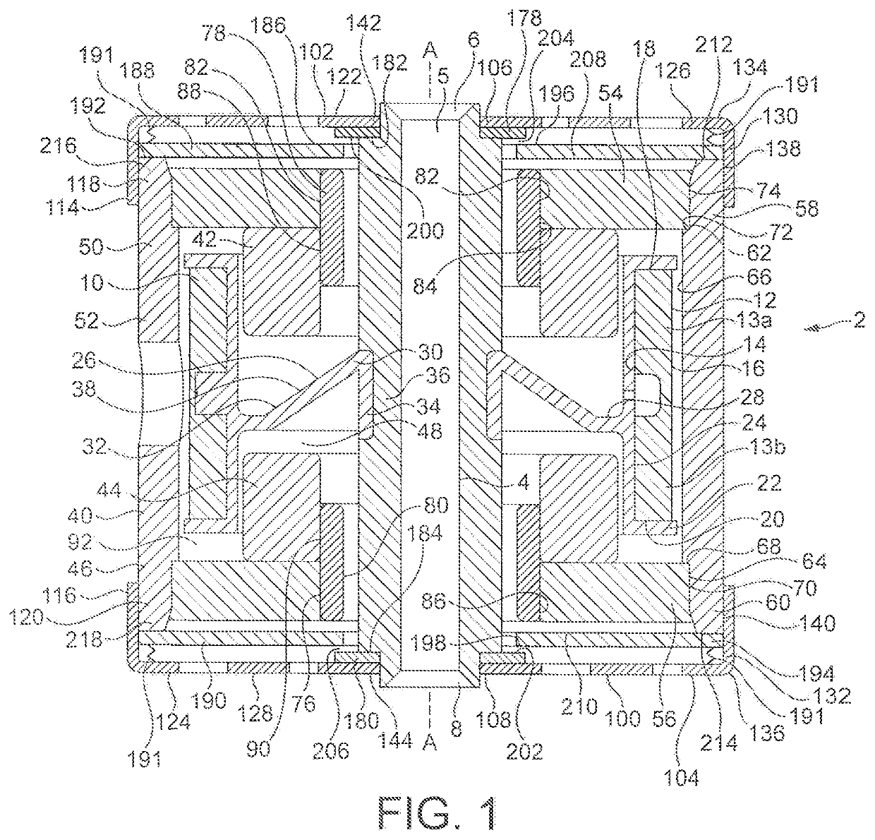
[0019]The electromechanical generator of the present invention is a resonant generator known in the art as “velocity-damped” where substantially all of the work done by the movement of the inertial mass relative to the housing is proportional to the instantaneous velocity of that movement. Inevitably, a portion of that work is absorbed overcoming unwanted mechanical or electrical losses, but the remainder of the work may be used to generate an electrical current via a suitable transduction mechanism, such as the electrical coil / magnetic assembly described below.

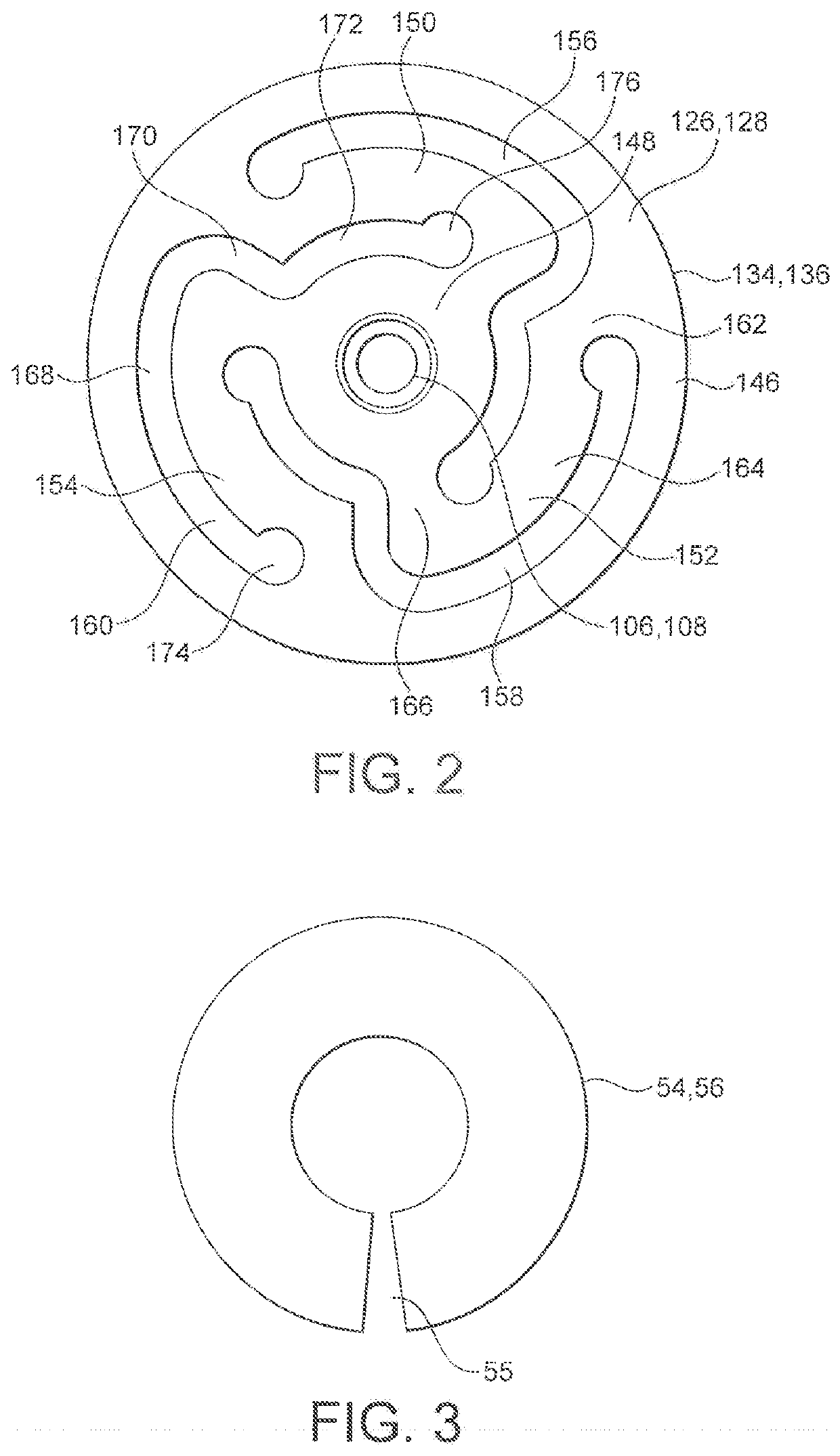
[0020]FIGS. 1 and 2 illustrate an electromechanical generator 2 for converting mechanical vibrational energy into electrical energy in accordance with a first embodiment of the present invention. In operation, the electromechanical generator 2 is enclosed within a housing (not shown) and the device is provided with a fitting (not shown) for securely mounting the electromechanical generator 2 to a support (not shown) from whic...


PUM


Abstract

An electromechanical generator for converting mechanical vibrational energy into electrical energy, the electromechanical generator comprising: a central mast, an electrically conductive coil assembly fixedly mounted to the mast, a magnetic core assembly movably mounted to the mast for linear vibrational motion a biasing device mounted between the mast and the magnetic core assembly, the biasing device comprising a pair of first and second plate springs, and a resilient device mounted between the biasing device and the magnetic core assembly, the resilient device being configured to be deformed between the biasing device and the magnetic core assembly when the magnetic core assembly has moved, by the linear vibrational motion, away from an equilibrium position by a predetermined non-zero threshold amplitude, the resilient device comprising a pair of first and second flat spring elements, each having an outer edge fitted to the magnetic core assembly and a free inner edge.

Description

BACKGROUND TO THE INVENTION[0001]The present invention relates to an electromechanical generator for converting mechanical vibrational energy into electrical energy, i.e. a vibration energy harvester. In particular, the present invention relates to such a vibration energy harvester which is a miniature generator capable of converting ambient vibration energy into electrical energy for use, for example, in powering intelligent sensor systems. Such a vibration energy harvester can be used in many areas where there is an economical or operational advantage in the elimination of power cables or batteries.DESCRIPTION OF THE PRIOR ART[0002]It is known to use vibration energy harvesters comprising an electromechanical generator for harvesting useful electrical power from ambient vibrations, e.g. for powering wireless sensors. A typical magnet-coil generator consists of a spring-mass combination attached to a magnet or coil in such a manner that when the system vibrates, a coil cuts through...

Claims


Application Information

Patent Timeline
Patent Type & Authority Applications(United States)
IPC IPC(8): H02K35/02
CPCH02K35/02H02K1/34F16F15/03H02K7/1876H02N2/186
Inventor WASENCZUK, ADAM
Owner PERPETUUM
Why Eureka
Try Eureka