Applying foliage and terrain features to architectural scaled physical models

a terrain feature and architectural scale technology, applied in the field of architectural scaled physical models, can solve the problems of difficult to evaluate the building model, no convenient method for easily evaluating the overall model iteratively, etc., and achieve the effect of facilitating repeated placement and removal

Inactive Publication Date: 2007-02-01
SWIFT LAWRENCE W
View PDF3 Cites 11 Cited by
  • Summary
  • Abstract
  • Description
  • Claims
  • Application Information

AI Technical Summary

Benefits of technology

[0010] According to embodiments of the present invention a method is provided for assembling a site model portion of an architectural which facilitates repeated placement and removal of miniature foliage to the model. The method includes construction of a site model with an shell portion and a base portion. The foliage is then attached to the shell portion. The shell portion of the site model is configured for removable attachment to the lower base portion. Thus, removal of the shell from the site model also allows the foliage to be removed from the site model in one motion leaving only the lower base. The foliage is replaced on the site model by replacement of the shell onto the lower base.
[0014] Still another aspect of this invention is to provide for an efficient and convenient method for attaching foliage to a site model which allows for easy and rapid removal and replacement of the foliage with respect to the site model.

Problems solved by technology

The problem with this traditional approach is that the model foliage placement on the site model portion of the architectural model often obscures views of design features of the building model portion of the architectural model.
When this happens it can be difficult to evaluate the building model without removing the foliage from the site model.
However, since the foliage is often either permanently attached or difficult to remove and later replace, there is no convenient method for easily evaluating the overall model iteratively both with and without foliage.

Method used


Image

  • Applying foliage and terrain features to architectural scaled physical models
  • Applying foliage and terrain features to architectural scaled physical models
  • Applying foliage and terrain features to architectural scaled physical models

Examples


Embodiment Construction

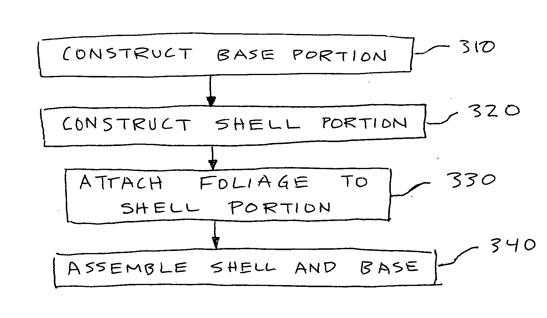
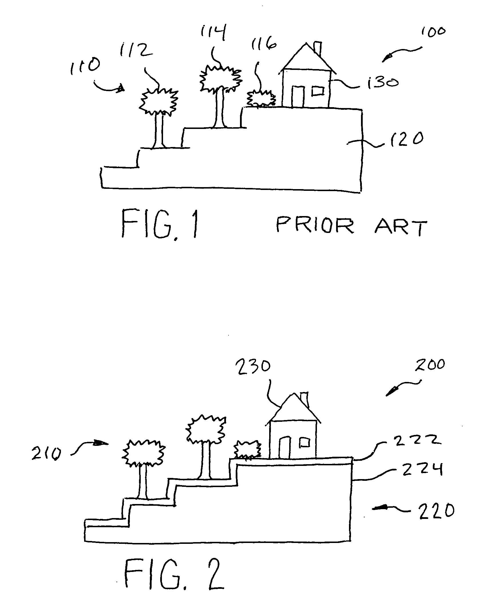
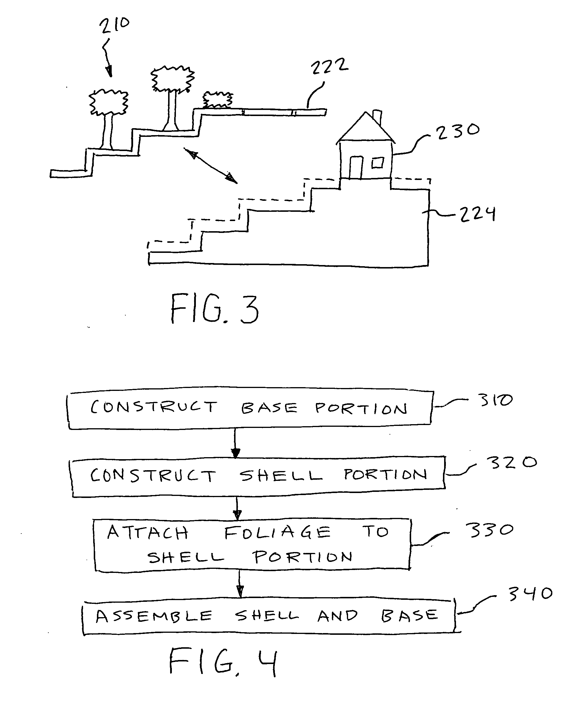
[0025] One embodiment of the present invention is a process by which model foliage can easily be detached and re-attached to a site model portion of an architectural model. This is in contrast to the traditional method of attaching foliage 110 to a site model portion 120 (refer to FIG. 1) of an architectural model 100, with miniature trees 112, 114 and shrubs 116 being attached to the site model 120 with glue, mechanical fasteners, or an interference fit provided by drilling a hole and jamming the miniature tree base into the hole.

[0026] A method according to the present invention avoids the difficulty of viewing and analysis of the building model 130 if the foliage 110 is permanently attached on the site model 120 and obscures the view of key elements of the building model 130 and cannot be easily moved out of the way. Removing and re-attaching the miniature trees 112, 114 and / or shrubs 116 that have been attached to the site model 120 via traditional methods can be extremely diff...


PUM


Abstract

The method for assembling an architectural site model facilitates repeated placement and removal of foliage to the model. The site model is constructed as an upper shell portion and a lower base portion. Model foliage is attached to the shell portion. The upper shell portion of the site model is configured for removable attachment to the lower base portion. Thus, removal of the shell from the site model also allows the foliage to be removed from the site model in one motion.

Description

CROSS REFERENCE TO RELATED APPLICATIONS [0001] This application claims priority benefit under 35 U.S.C. § 119(e) from provisional application No. 60 / 698,708, filed Jul. 13, 2005. The 60 / 698,708 application is incorporated by reference herein, in its entirety, for all purposes. [0002] This application also relates to co-pending applications by the same inventor of this application and entitled “Building of Scaled Physical Models” (application no. ______, filed ______), “Identification of Terrestrial Foliage Location, Type, and Height for Architectural Models” (application no. ______, filed ______), and “Determination of Scaling for Architectural Models” (application no. ______, filed ______)FIELD OF THE INVENTION [0003] The invention relates generally to architectural processes of building physical models to develop and communicate building design concepts. In particular, the invention relates to a process for preparing a physical foliage representation relating to a site model, atta...

Claims


Application Information

Patent Timeline
Patent Type & Authority Applications(United States)
IPC IPC(8): G06F17/50
CPCG09B25/08G09B25/04B33Y80/00B33Y50/00
Inventor SWIFT, LAWRENCE W.
Owner SWIFT LAWRENCE W
Why Eureka
Try Eureka