Unlock instant, AI-driven research and patent intelligence for your innovation.
Home server
Inactive Publication Date: 2007-02-01
SANYO ELECTRIC CO LTD
View PDF10 Cites 11 Cited by
Summary
Abstract
Description
Claims
Application Information
AI Technical Summary
This helps you quickly interpret patents by identifying the three key elements:
Problems solved by technology
Method used
Benefits of technology
Benefits of technology
[0011] According to this characteristic, it becomes possible to allow a user of a home network, who does not have much knowledge of the cooperative control, to recognize through a screen on the control terminal which operation contents are realized, that is, whether or not convenience of the home network is enhanced by connecting which apparatus (the second apparatus) to the home network in addition to an apparatus (the first apparatus) already having been connected to the home network.
[0012] In other words, according to this characteristic, utilization of the cooperative control in a home network can be promoted, whereby a chance of newly purchasing the apparatus can be created.
Problems solved by technology
Therefore, it is not easy for a user of the home network, who does not have much knowledge of the cooperative control, to recognize what operation content is realized by cooperating which apparatus and which apparatus.
As a result, there has been a problem that the cooperative control often cannot be fully utilized.
Method used
Image
Click on the blue label to locate the original text in one second.
Reading with bidirectional positioning of images and text.
Examples
first embodiment
[First Embodiment]
[0034] A first embodiment of the present invention will be described below.
(Configuration of Home Network Including Home Server)
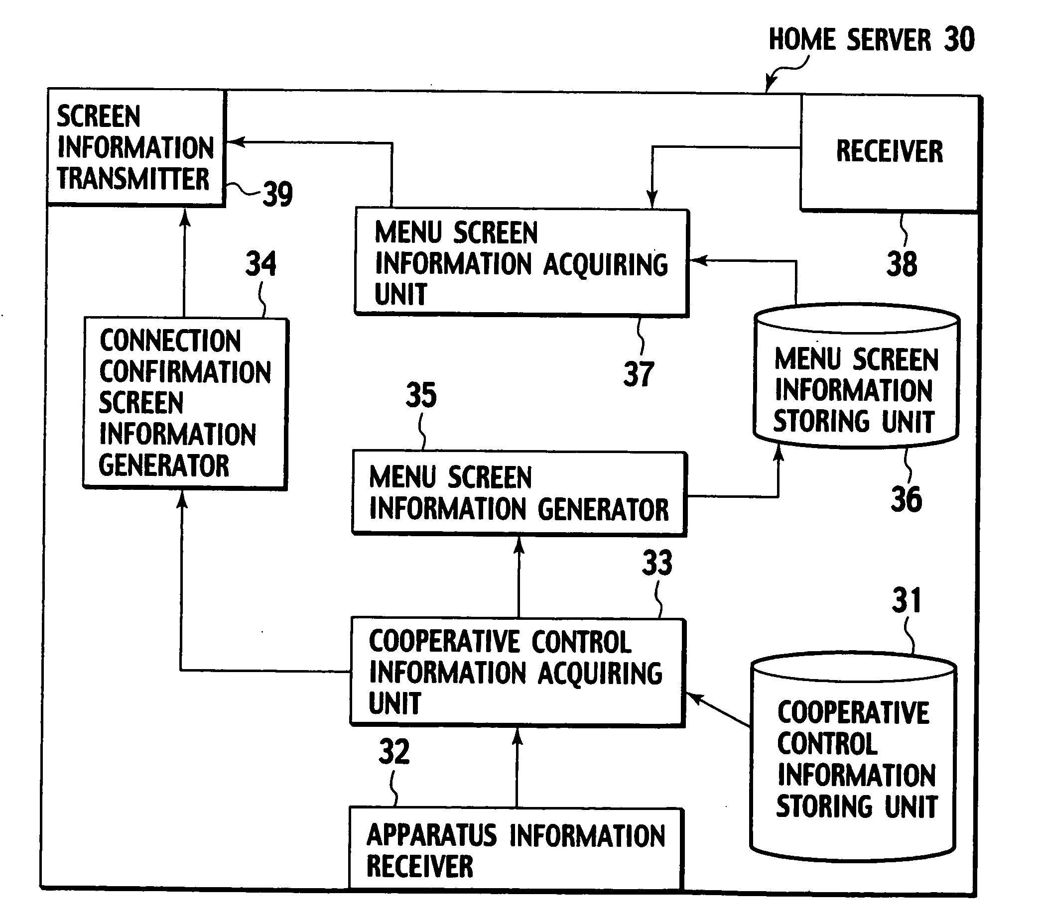
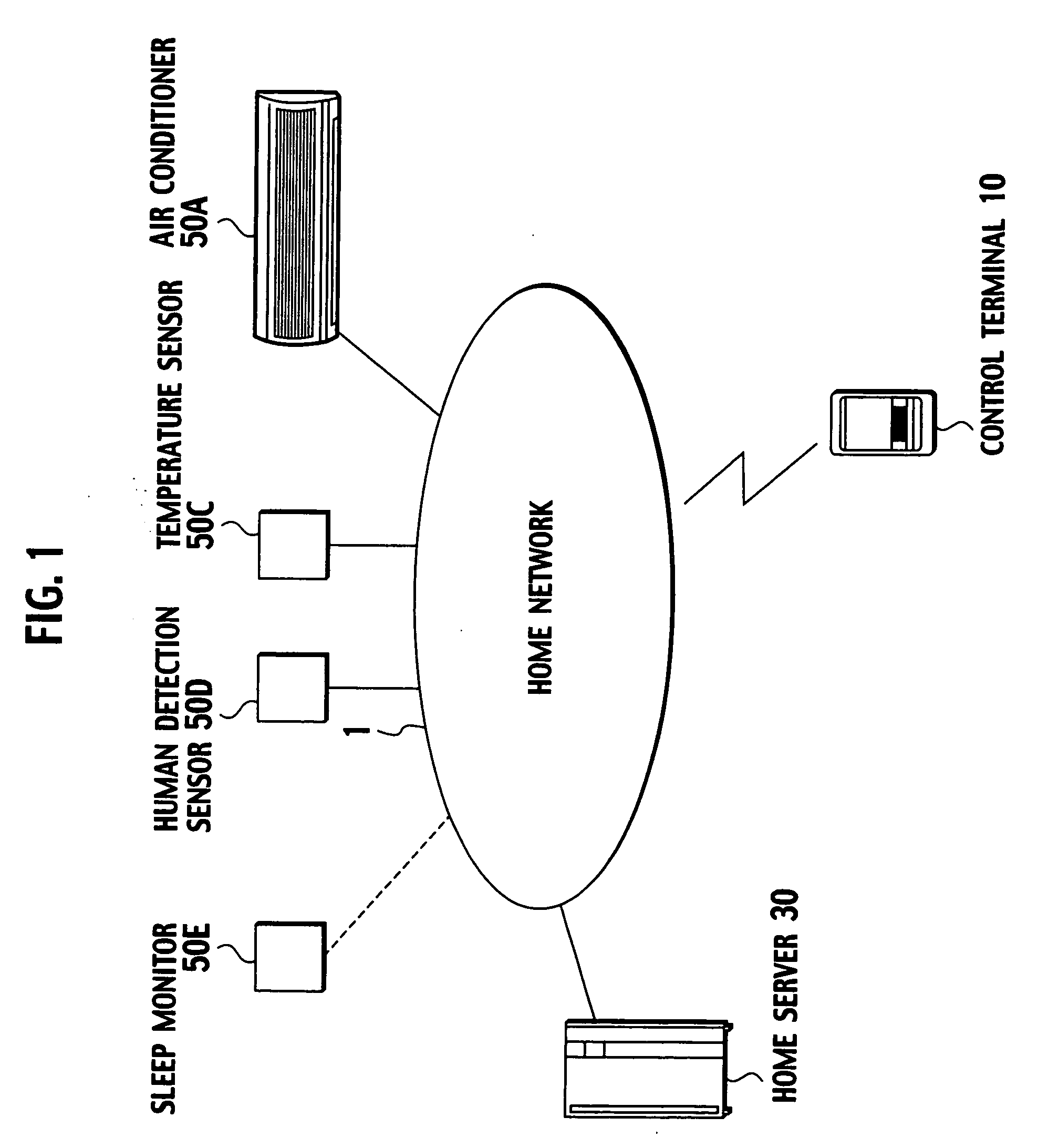
[0035] First, a configuration of a home network including a home server according to this embodiment will be described. FIG. 1 is a configuration diagram of a home network 1, which includes a home server 30 according to this embodiment.
[0036] As shown in FIG. 1, a plurality of apparatuses (clients), for example, an air conditioner 50A, a temperature sensor 50C, a human detection sensor 50D, and a sleep monitor 50E (as appropriate, each of which will be referred to as the “client 50” for short), are connected to the home network 1. The temperature sensor 50C, the human detection sensor 50D and the sleep monitor 50 can operate through linkage with the air conditioner 50A.
[0037] Additionally, a control terminal 10 and the home server 30 are also connected to the home network 1.
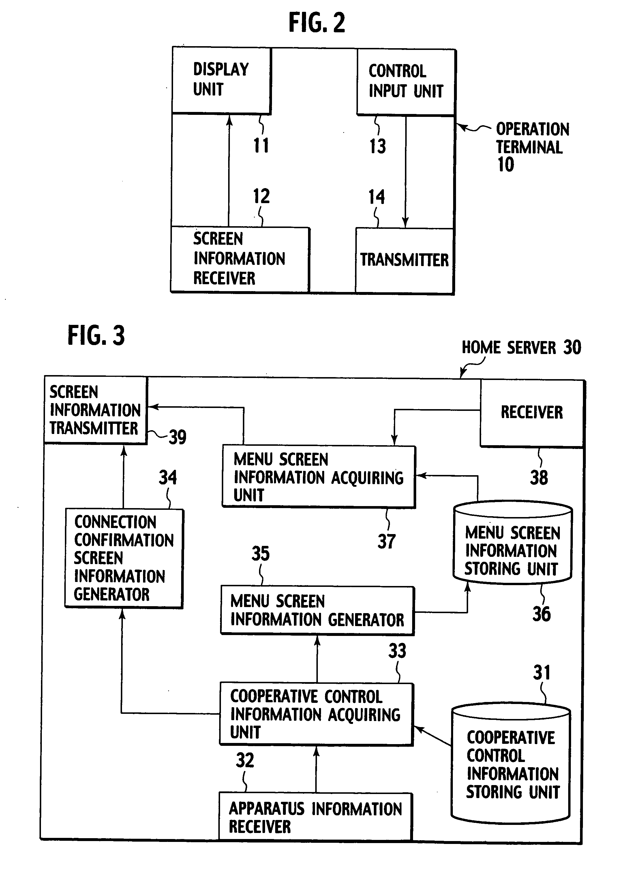
[0038] The control terminal 10 is a remote control terminal ...
second embodiment
[Second Embodiment]
[0089] Next, a second embodiment of the present invention will be described. In this embodiment, cooperative control is executed with respect to audio-visual apparatuses such as a television receiver and a network camera. Additionally, in this embodiment, it is possible to display detail information on an apparatus which can operate through linkage with the other apparatus, and to promote a purchase of the apparatus.
(Configuration of Home Network Including Home Server)
[0090]FIG. 8 is a configuration diagram of the home network 1, which includes a home server 30A according to this embodiment. Note that, the following descriptions will be given mainly of portions in which this embodiment differs from the first embodiment, and descriptions on the corresponding portions will be omitted as appropriate.
[0091] As shown in FIG. 8, a television receiver 50F is connected to the home network 1 in this embodiment. Additionally, an external network 2 is connected to the ho...
PUM
Abstract
A home server according to the present invention transmits a screen information including a second apparatus identification information identifying a second apparatus and which correlates with a first apparatus identification information identifying a first apparatus, and operation contents realized through linkage of the first apparatus and the second apparatus.
Description
CROSS-REFERENCE TO RELATED APPLICATIONS [0001] This application is based on and claims the benefit of priority from the prior Japanese Patent Applications No. P2005-117369, filed on Apr. 14, 2005 and P2006-110079, filed on Apr. 12, 2006; the entire contents of which are incorporated herein by reference. BACKGROUND OF THE INVENTION [0002] 1. Field of the Invention [0003] The present invention relates to a home server connected to a home network along with a plurality of apparatuses operated by a control terminal. [0004] 2. Description of the Related Art [0005] As one of characteristics of a home network system placed inside of premises such as a house, there can be cited cooperative control where a plurality of apparatuses (clients) are operated by allowing them in conjunction with one another (for example, Japanese Patent Application publication No. 2003-22224 (pp. 4-6, FIGS. 4 and 5)). [0006] As one example of the cooperative control, there can be cited automated control such as co...
Claims
Application Information
Patent Timeline
Application Date:The date an application was filed.
Publication Date:The date a patent or application was officially published.
First Publication Date:The earliest publication date of a patent with the same application number.
Issue Date:Publication date of the patent grant document.
PCT Entry Date:The Entry date of PCT National Phase.
Estimated Expiry Date:The statutory expiry date of a patent right according to the Patent Law, and it is the longest term of protection that the patent right can achieve without the termination of the patent right due to other reasons(Term extension factor has been taken into account ).
Invalid Date:Actual expiry date is based on effective date or publication date of legal transaction data of invalid patent.

