Cutting device

Inactive Publication Date: 2007-02-08
VOITH PATENT GMBH
View PDF7 Cites 9 Cited by
  • Summary
  • Abstract
  • Description
  • Claims
  • Application Information

AI Technical Summary

Benefits of technology

[0008] It is the object of the present invention to propose a cutting device in w

Problems solved by technology

The deposits of cut material on the base support can lead to disruption to the transport of the cut materi

Method used


Image

  • Cutting device
  • Cutting device
  • Cutting device

Examples


Example

[0032] The particulars shown herein are by way of example and for purposes of illustrative discussion of the embodiments of the present invention only and are presented in the cause of providing what is believed to be the most useful and readily understood description of the principles and conceptual aspects of the present invention. In this regard, no attempt is made to show structural details of the present invention in more detail than is necessary for the fundamental understanding of the present invention, the description taken with the drawings making apparent to those skilled in the art how the several forms of the present invention may be embodied in practice.

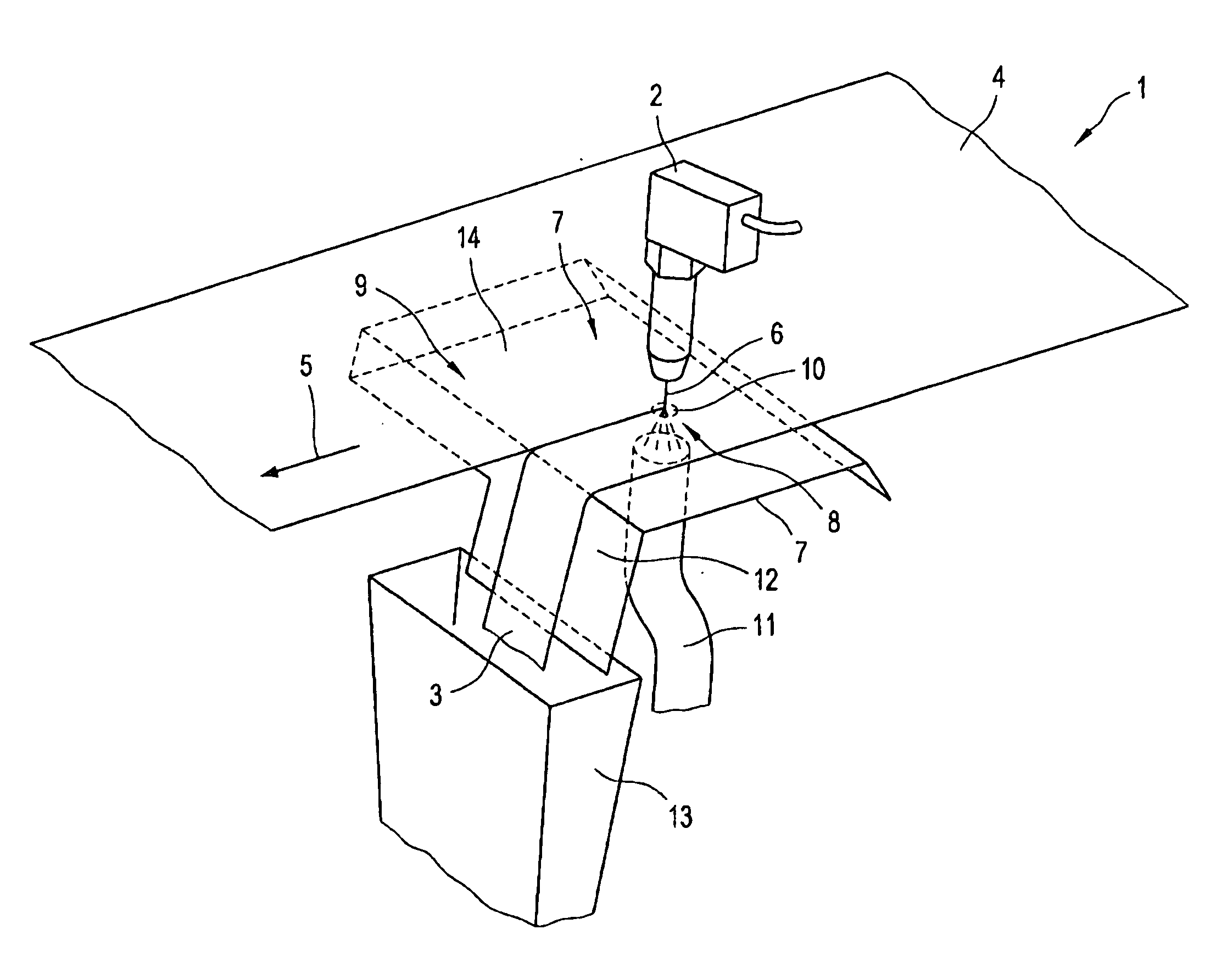
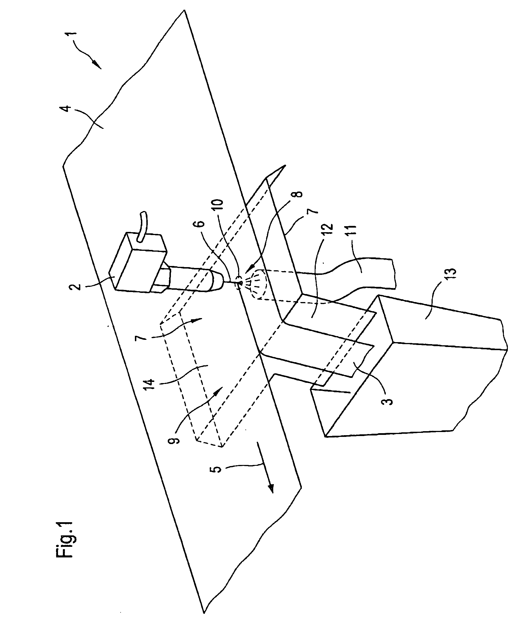
[0033]FIG. 1 shows a cutting device 1 disclosed by the prior art.

[0034] The cutting device 1 has a cutting unit 2 for dividing a strip 3 from a material web 4 running in a transport direction 5 relative to the cutting device 1. The transport direction 5 of the material web 4 runs parallel to the longitudinal extent of ...


PUM

PropertyMeasurementUnit
Angleaaaaaaaaaa
Electrical resistanceaaaaaaaaaa
Transport propertiesaaaaaaaaaa

Abstract

The invention relates to a cutting device having a cutting unit for dividing a strip from a material web running in a transport direction relative to the cutting device, and having a base support that defines a cutting section for supporting the material web during the division of the strip, and a supporting section, the supporting section being formed and arranged in such a way that it supports the material web and the strip as they are transported away out of the cutting section in the transport direction, wherein the supporting section has a cutout which extends and is formed in such a way that the cut edge of the material web and/or the cut edge of the strip are not supported on the supporting section, at least in some sections, as they are transported away out of the cutting section.

Description

CROSS-REFERENCE TO RELATED APPLICATIONS [0001] The present application claims priority under 35 U.S.C. §119 of German Patent Application No. 10 2005 018 767.6 filed on Apr. 22, 2005, the disclosure of which is expressly incorporated by reference herein in its entirety. BACKGROUND OF INVENTION [0002] 1. Field of the Invention [0003] This invention relates to a cutting device for dividing a strip from a material web moving in a transport direction relative to the cutting device, according to the preamble of patent claim 1. [0004] 2. Discussion of Background Information [0005] Such cutting devices are generally found in machines for the production and / or further processing of a material web, in particular a fibrous web such as paper, board or tissue, in order preferably to divide an edge strip running parallel to the longitudinal extent of the material web from the material web. Such cutting devices normally have a cutting unit which, for example, produces a cutting jet which acts on t...

Claims


Application Information

Patent Timeline
IPC IPC(8): B26D7/06
CPCB26D7/1863B26D7/20B26F3/008B26F3/004B26D2007/0068Y10T83/2066
Inventor BRODBEK, HARTMUTSCHNEIDER, WOLFGANGDREFS, WOFGANG
Owner VOITH PATENT GMBH
Why Eureka
Try Eureka