Sleeve element for axially fixing a bearing and exhaust gas turbocharger

a technology of axial fixing and bearing, applied in the direction of machines/engines, bearing unit rigid support, liquid fuel engines, etc., can solve the problems of greatly increasing effort, and achieve the effect of reducing assembly costs, reducing total costs, and reducing total costs

Inactive Publication Date: 2012-03-15
DAIMLER AG
View PDF6 Cites 5 Cited by
  • Summary
  • Abstract
  • Description
  • Claims
  • Application Information

AI Technical Summary

Benefits of technology

[0016]A further reduction of assembly costs and therefore total costs is achieved by providing that, according to a particularly advantageous aspect of the invention, the at least one through-opening is extended to at least one edge of the sleeve element in the axial direction of the sleeve element. This means that the sleeve element comprises at least one through-opening designed according to the invention which is not closed in at least one axial direction, so that the speed detection device can be installed before the installation of the sleeve element. Through the conical through-opening, the spacer sleeve can automatically be turned into the correct position relative to the speed detection device by axial displacement. This embodiment of the invention offers a further reduction of assembly time and thus assembly costs, so that total costs can be reduced further. By means of the sleeve element, an axial location of a bearing can nevertheless be implemented for the optimum bearing-mounting of the shaft of the turbocharger, which is useful because a turbocharger shaft develops very high speeds in operation and therefore requires a highly effective bearing mounting in order to minimize wear and the probability of failure.
[0017]In a turbocharger for an internal combustion engine, which comprises a speed detection device and a sleeve element for the axial location of at least one bearing of a shaft of the turbocharger, wherein the sleeve element has at least one through-opening in its circumferential surface through which the speed detection device passes through the sleeve element, the invention provides that the at least one through-opening has in the radial direction of the sleeve element a substantially conical shape at least in a section thereof. Owing to this conical design of the through-opening of the sleeve element, all of the advantages already described in the context of the sleeve element according to the invention can be obtained, i.e. the advantages of a simplified and cost-effective assembly by avoiding further processing, because a quasi-independent orientation of the sleeve element is achieved in the radial direction during the installation of the speed detection device.
[0018]In a particularly advantageous embodiment of the turbocharger the at least one through-opening has in the axial direction of the sleeve element a substantially conical shape at least in a section thereof. Owing to this, all of the advantages described above in the context of the sleeve element according to the invention can be transferred to the turbocharger, so that the total costs of the turbocharger can be reduced owing to a further simplification of the assembly process.
[0019]The same applies to a further advantageous embodiment in which the at least one through-opening is extended to at least one edge of the sleeve element in the axial direction of the sleeve element. The sleeve element therefore has a through-opening which is not closed in at least one axial direction, so that the speed detection device can be built in before an installation of the sleeve element. For the easy detection of a speed of a shaft of the turbocharger according to the invention, the sleeve element can be rotated into a correct position in a simple way through the through-opening by axial displacement by the speed detection device, allowing an efficient and effective control of the turbocharger for instant adaptation to operating points of the corresponding internal combustion engine. As a result of this efficient and effective adaptability, the fuel consumption and therefore the CO2 emissions of the internal combustion engine can be reduced considerably.
[0020]If the sleeve element is located via the at least one through-opening by means of the speed detection device, this arrangement is extremely advantageous in that it makes additional fastening elements and measures obsolete, which reduces the total costs of the turbocharger, because the assembly effort is further reduced. This fixing of the sleeve element by means of the speed detection device in particular relates to a rotational location. For this purpose, a geometry of the through-opening of the sleeve element has to have a particular advantageous relationship with the dimensions of the speed detection device. This means that a contour or a shape of the through-opening is matched to a corresponding external contour or shape of the speed detection device.
[0021]In a further aspect of the turbocharger according to the invention, the sleeve element is arranged between two bearings, specifically radial bearings, of the shaft. This results in a relatively large scope for the provision of the through-opening according to the invention, whereby the design and the spatial arrangement of the speed detection device are made significantly more flexible. As a result, package problems can be solved, which is particularly advantageous in space-critical applications, such as in an engine compartment into which a turbocharger according to the invention is installed as a rule.

Problems solved by technology

The subsequent alignment of the spacer sleeve according to prior art can be achieved only conditionally and involves a greatly increased effort owing to a lack of accessibility.

Method used


Image

  • Sleeve element for axially fixing a bearing and exhaust gas turbocharger
  • Sleeve element for axially fixing a bearing and exhaust gas turbocharger
  • Sleeve element for axially fixing a bearing and exhaust gas turbocharger

Examples


Embodiment Construction

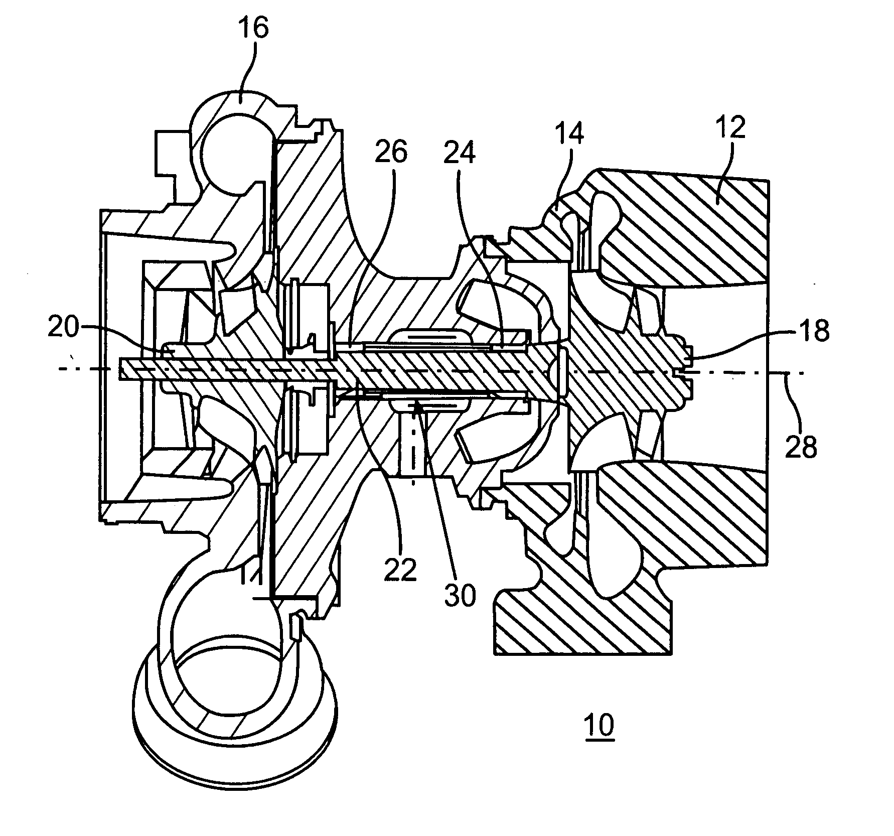
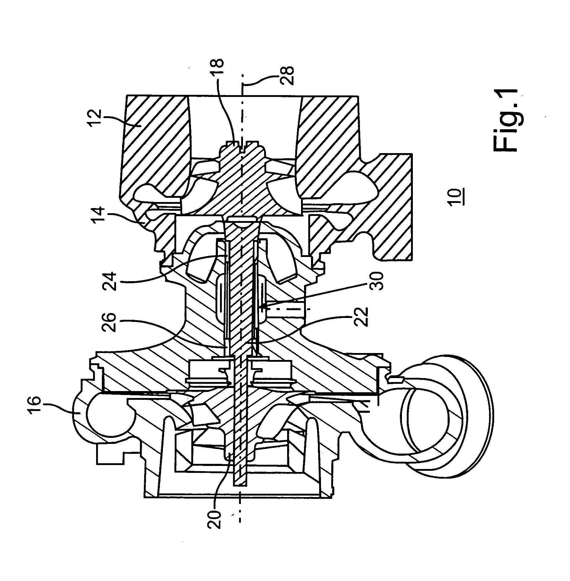
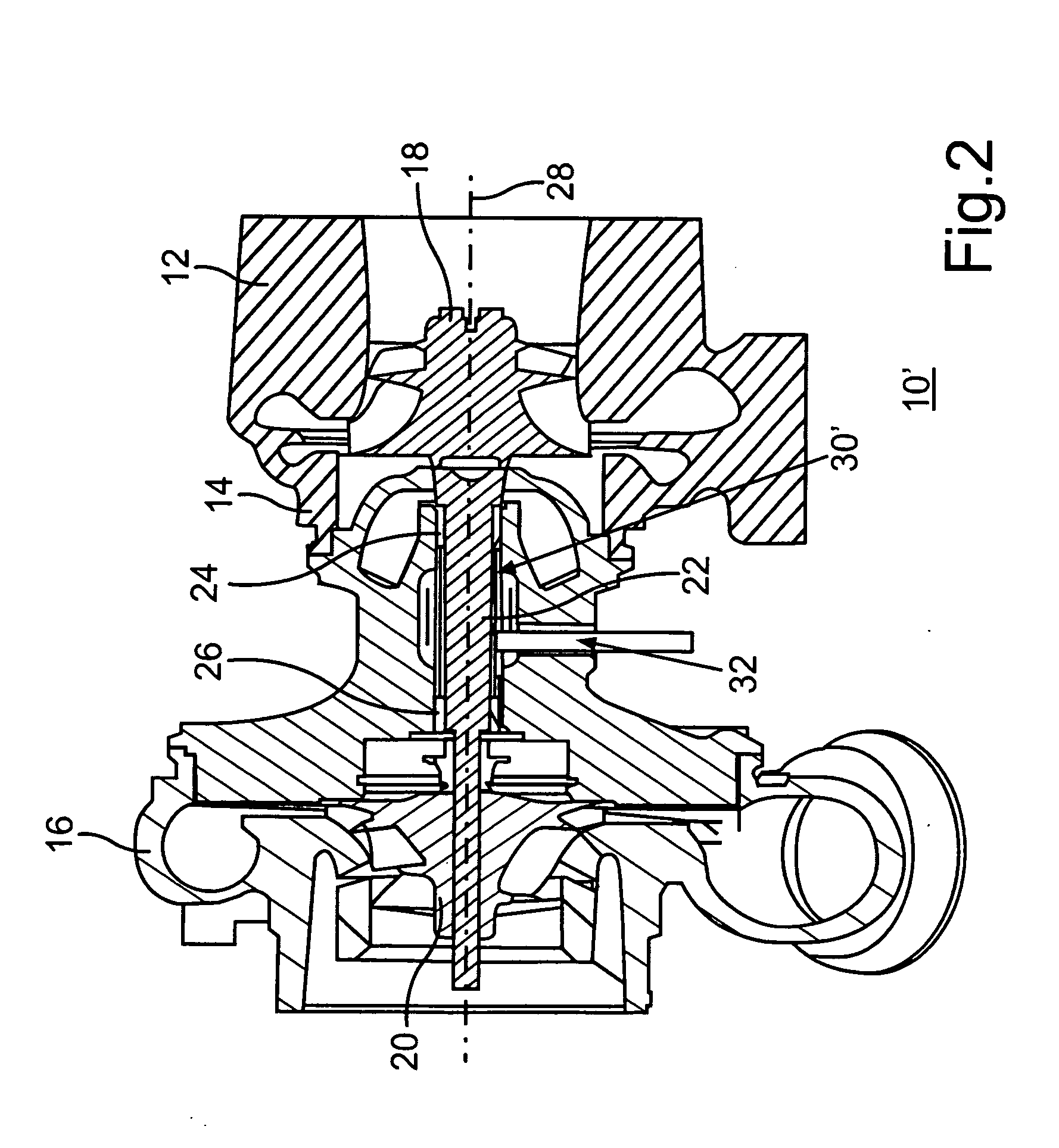
[0028]While FIGS. 1 and 2 show turbochargers with a sleeve element for the axial location of two radial bearing bushes according to prior art, FIGS. 3 to 5 show alternative embodiments of a sleeve elements of this type which are intended to simplify the installation of a speed detection device for a turbocharger.

[0029]FIGS. 3A to 3C show a sleeve element 40 having a hollow-cylindrical shape. The sleeve element 40 is used for the axial location of at least one bearing of a rotatable shaft, in particular a shaft of a turbocharger, As a rule, however, it is used for the axial location of two bearings of the rotatable shaft in such a way that the sleeve element supports one bearing with one end face 42 and another bearing with its opposite end face 44, thereby axially locating these bearings.

[0030]In its circumferential surface 46, the sleeve element 40 has a through-opening 48 which in a top view essentially has the shape of a slot. The through-opening 48 has the purpose of ensuring th...


PUM


Abstract

In a sleeve element for the axially fixing at least one bearing of a rotatable shaft, in particular a shaft of an exhaust gas turbocharger, which sleeve element has at least one through-opening in its circumferential surface, the at least one through-opening has a substantially conical shape in the radial direction of the sleeve element at least in a section thereof, and also in a turbocharger for an internal combustion engine, which comprises a speed detection device and a sleeve element for axially fixing at least one bearing of a shaft of the turbocharger, wherein the sleeve element has at least one opening through which the speed detection device extends and which has a substantially conical shape in the radial direction of the sleeve element at least in a section thereof.

Description

[0001]This is a Continuation-In-Part application of pending international patent application PCT / EP2010 / 002058 filed Mar. 31, 2010 and claiming the priority of German Patent application 10 2009 016 688 / 2 filed Apr. 7, 2009.BACKGROUND OF THE INVENTION[0002]The invention relates to a sleeve element for axially fixing a bearing and to an exhaust gas turbocharger for an internal combustion engine including such a sleeve element.[0003]Such sleeve elements and turbochargers are known and shown in FIGS. 1 and 2.[0004]FIG. 1 shows a turbocharger 10 for an internal combustion engine, comprising a turbine housing 12, a bearing housing 14 and a compressor housing 16. The turbine housing 12 accommodates a turbine wheel 18 and the compressor housing 16 accommodates a compressor impeller 20, these two components being connected to each other by a shaft 22. The shaft 22 is mounted in the bearing housing 14 by means of radial bearing bushes 24 and 26. In the axial direction along an axis of rotatio...

Claims


Application Information

Patent Timeline
Patent Type & Authority Applications(United States)
IPC IPC(8): F16C33/04F02B33/40
CPCF02C6/12F05D2240/50F04D29/0563F16C35/02F16C17/02F16C17/18F16C2360/24
Inventor HERTWECK, GERNOTSEUFFERT, JOHANNES
Owner DAIMLER AG
Why Eureka
Try Eureka