Method for transmitting data via shared relay station in mobile communication system

Inactive Publication Date: 2015-01-29
KOREA UNIV RES & BUSINESS FOUND
View PDF3 Cites 5 Cited by
  • Summary
  • Abstract
  • Description
  • Claims
  • Application Information

AI Technical Summary

Benefits of technology

[0022]According to one embodiment of the present invention, when terminals located in adjacent cells transmit data in a cellular mobile communication network where two or more base stations share

Problems solved by technology

Although the maximum possible wireless transfer rate has been so far rapidly increased through OFDM (Orthogonal Frequency Division Multiplexing) techniques and MIMO (Multi-Input Multi-Output) techniques, the bandwidth efficiency has not yet been increased proportionally.
In particular, in cellular systems using OFDMA (Orthogonal Frequency Division Multiple Access) such as IEEE 802.16e-based mobile WiMAX or 3GPP LTE, transfer rates of individual terminals are unavoidably limited by deterioration of CINR (Carrier to Interference and Noise Ratio) at cell edges, which may result in poor bandwidth efficiency of the overall system.
However, at boundaries of adjacent wireles

Method used


Image

  • Method for transmitting data via shared relay station in mobile communication system
  • Method for transmitting data via shared relay station in mobile communication system
  • Method for transmitting data via shared relay station in mobile communication system

Examples


Embodiment Construction

[0028]Hereinafter, preferred embodiments of the present invention will be described in detail with reference to the accompanying drawings.

[0029]In the following detailed description of the present invention, concrete description on related functions or constructions will be omitted if it is deemed that the functions and / or constructions may unnecessarily obscure the gist of the present invention. Terminologies used herein are terms to provide proper expression of preferred embodiments of the present invention and may have different meanings depending on intention of users or operators or practices in the related art. Therefore, the definition of the terminologies should be made on the basis of contexts throughout the specification. Throughout the drawings, the same members are denoted by the same reference numerals.

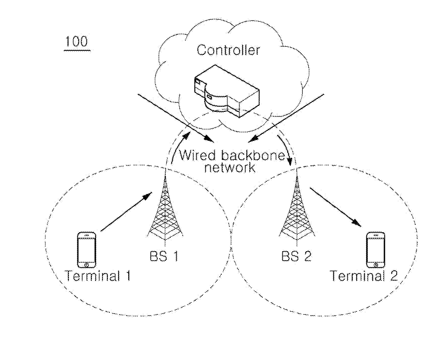
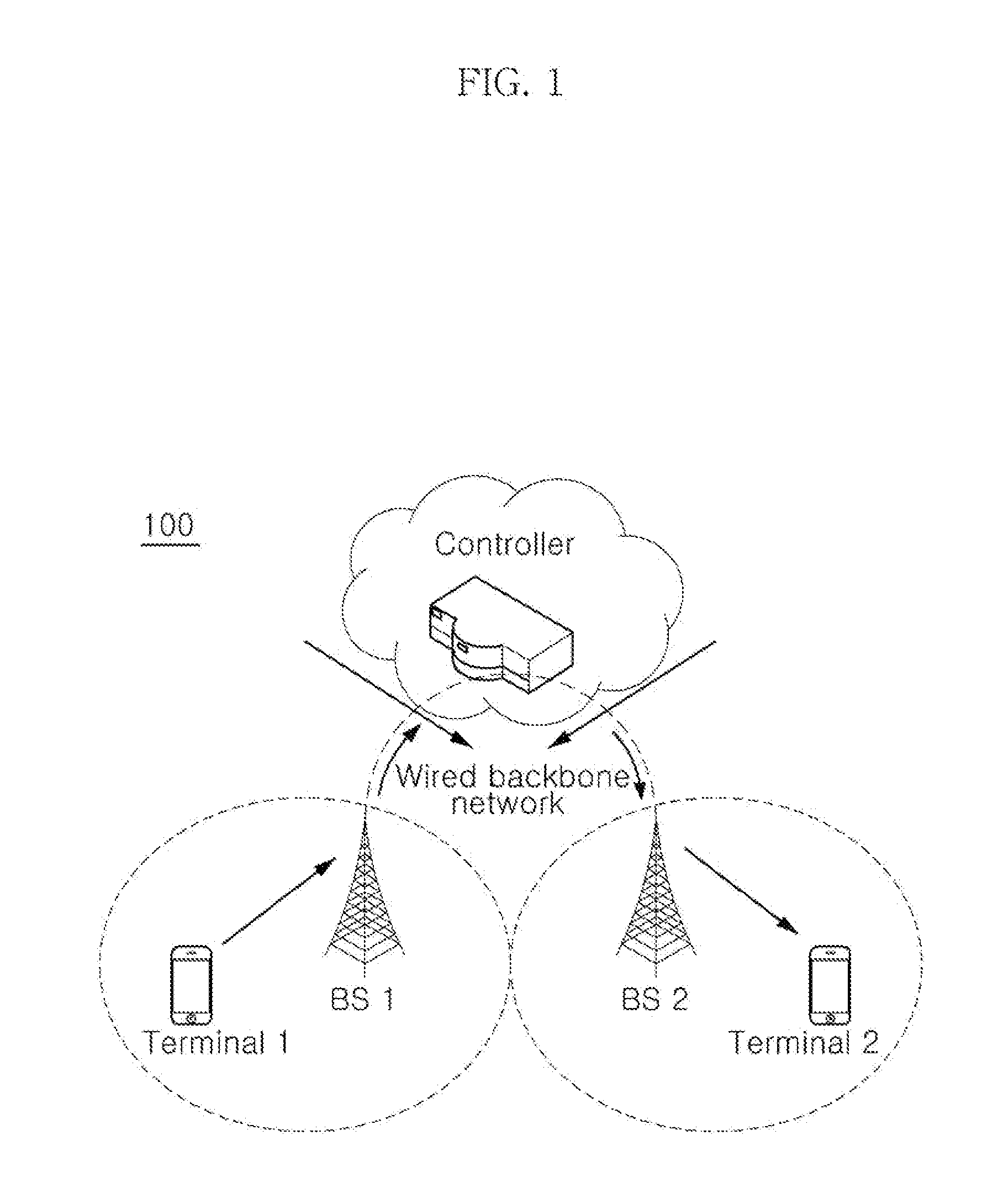
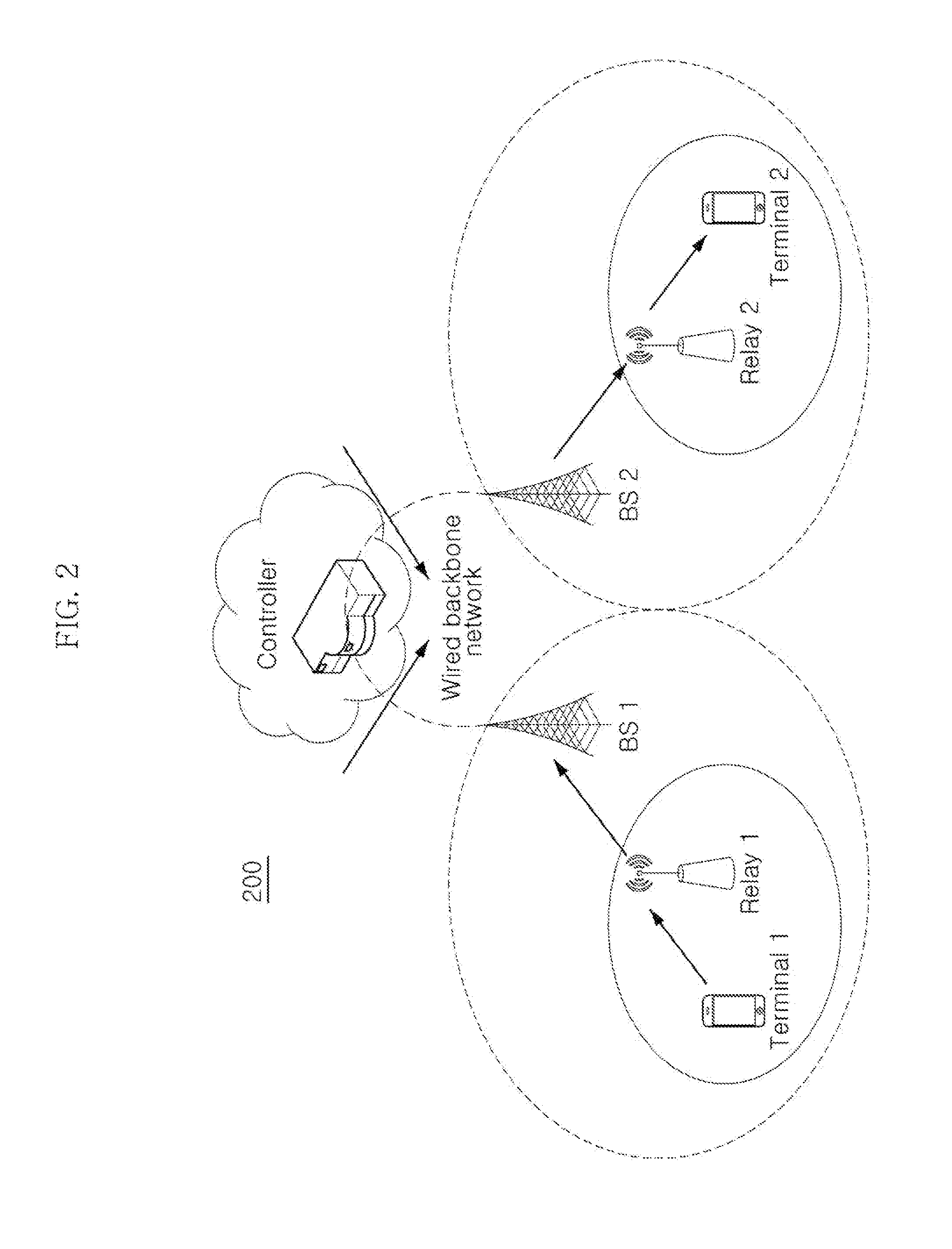
[0030]In a system using a shared relay station suggested by the present invention, two or more base stations share one wireless relay station, as opposed to an existing w...


PUM


Abstract

The present invention relates to a transmitting method for minimizing the delay time for data transmission via a wired backbone network using a shared relay station (SRS), wherein the steps of transmitting data and control information using the shared relay station comprises: a) sharing a relay station between at least two base stations (BS) and b) transmitting data via at least two base stations, terminals connected to the respective base stations, and a relay station. According to the present invention, the delay time for data transmission is minimized in comparison with conventional cellular networks, as data which was transmitted to a controller of a core network via a wired backbone network in the conventional cellular networks is transmitted to base stations or terminals via a wireless link by means of a shared relay station.

Description

TECHNICAL FIELD[0001]This invention relates to a transmission technique for minimizing delay time for data transmission via wired backbone network using a shared relay station (SRS).BACKGROUND ART[0002]As smartphones and a variety of multimedia application services are booming, there is a demand for advanced cellular networks to accommodate fast-growing data traffics.[0003]In particular, in order to secure economical cellular networks, bandwidth efficiency has to be maximized by increasing the maximum wireless transfer rate and an average throughput. Although the maximum possible wireless transfer rate has been so far rapidly increased through OFDM (Orthogonal Frequency Division Multiplexing) techniques and MIMO (Multi-Input Multi-Output) techniques, the bandwidth efficiency has not yet been increased proportionally.[0004]In particular, in cellular systems using OFDMA (Orthogonal Frequency Division Multiple Access) such as IEEE 802.16e-based mobile WiMAX or 3GPP LTE, transfer rates ...

Claims


Application Information

Patent Timeline
IPC IPC(8): H04W72/04H04B7/15
CPCH04B7/15H04W72/042H04W84/047H04W92/045H04W16/26H04B7/15528H04B7/2606H04B7/14H04W72/23
Inventor RYU, HYUN SEOKKANG, CHUNG GU
Owner KOREA UNIV RES & BUSINESS FOUND
Why Eureka
Try Eureka