Hair clip provided with a podium

a technology of hair clips and podiums, applied in the field of hair clips, can solve the problems of affecting the handling of these levers and contributing to the easy handling of the clip by users, and achieve the effect of reducing the size and facilitating the handling of the hair clip

Inactive Publication Date: 2007-02-08
CORAL HILAIRE
View PDF5 Cites 17 Cited by
  • Summary
  • Abstract
  • Description
  • Claims
  • Application Information

AI Technical Summary

Benefits of technology

[0010] The object of the invention is to modify a hair clip of the type previously described, in order to reduce the size required by the presence of the support plate, in particular in the opening position. The purpose of the invention is thus easier handling of the hair clip.
[0014] According to a preferred embodiment, the lugs are engaged with the inner walls of the two shells and extend between the two shell hinges and between two rear edges of the shells which clamp around the lugs as the support plate is lifted relative to the axial direction of pivoting, when the two shells pivot from the closure position to the opening position. The securing onto the inner walls of the two shells contributes towards protecting the podium, which is less exposed.
[0016] This arrangement makes it possible to control the lifting of the podium in a first stage with a low level of lifting, whilst the two lugs intersect, and in a second stage with a high level of lifting, when the bent parts of the two lugs coincide with one another. This arrangement also decreases the size of the podium and reduces the spacing between the two rear edges of the two shells which is necessary for the two lugs to extend.

Problems solved by technology

The articulation of the support plate on the levers themselves appears to impede the handling of these levers for the purpose of opening the hair clip.
In addition, the pivoting of the support plate relative to the levers increases the size of the clip from the front to the rear in the opening position, which also does not seem to contribute to easy handling of the clip by a user.

Method used


Image

  • Hair clip provided with a podium
  • Hair clip provided with a podium
  • Hair clip provided with a podium

Examples


first embodiment

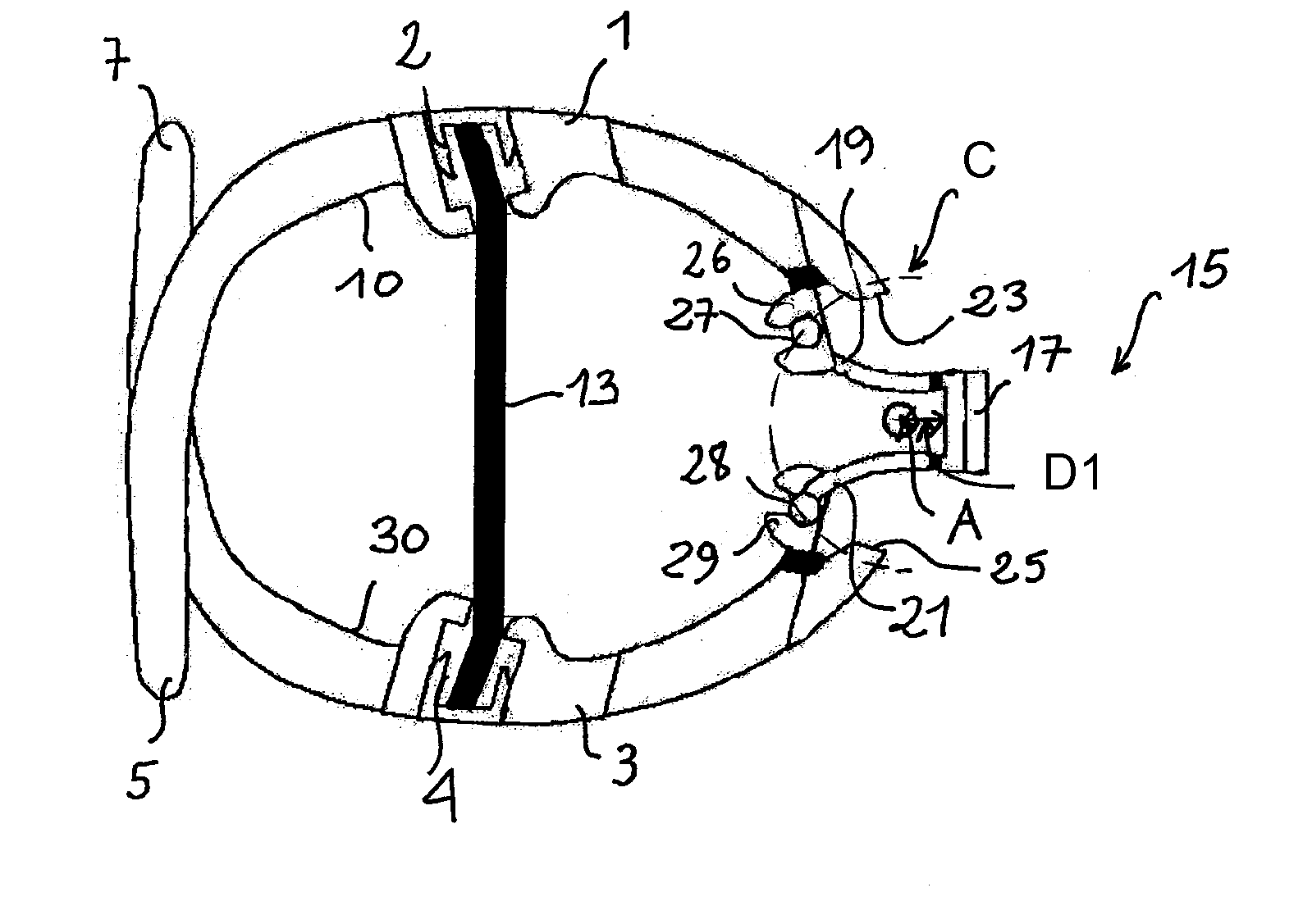
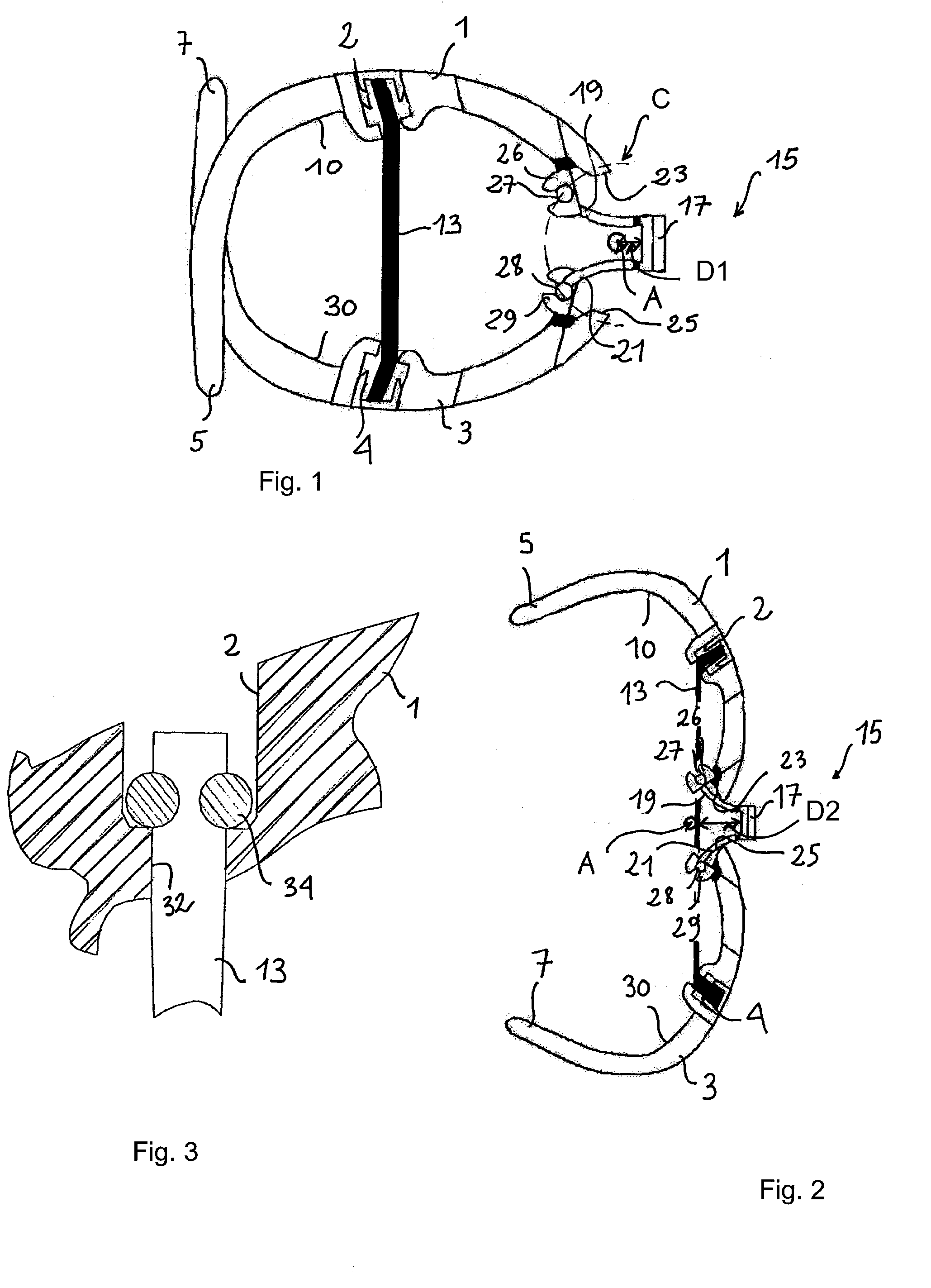
[0049] According to the invention, which is illustrated more particularly by FIGS. 1 and 2, the two lugs 19, 21 of the podium 15 each extend on one side of the support plate 17 without intersecting.

second embodiment

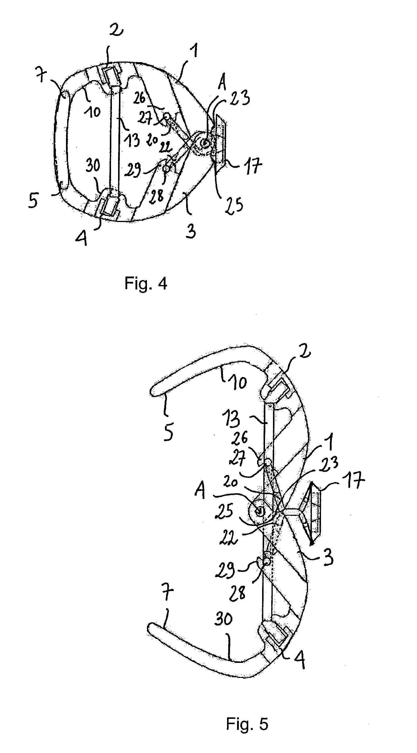
[0050] which is illustrated more particularly by FIGS. 4 and 5, and details of which are given in FIGS. 9 and 10, the two lugs 20, 22 of the podium 15 are fitted head to tail, and are bent at first bends 16, 18 and second bends 6, 8 in order to intersect when the clip is in the closure position, FIG. 9, and to coincide between the rear edges of shells 23, 25 when the clip is in the opening position, FIG. 10. For each of the two lugs 20, 22, the coincidence concerns the portion which is contained between the first bend 6, 8 and the second bend 16, 18. As previously stated, the lifting of the podium 15 is thus controlled in a first stage with a low level of lifting, during which the two lugs 20, 22 still intersect, and in a second stage it is controlled with a high level of lifting, when the portions contained between the first and second bends coincide with one another. This arrangement reduces the size of the podium 15 and reduces the spacing between the edges 23, 25 of the two she...

third embodiment

[0052] According to the invention, FIGS. 13 to 16, the lugs of the podium are provided with stops 39, 41 which abut one another when the two lugs intersect in the closure position of the shells. By means of this arrangement, the lugs of the podium limit the course of pivoting of the two shells into the closure position. As a result, when the two claws are designed to intersect in the closure position, they themselves no longer form a stop. In other words, the return of the two shells to the closure position no longer leads to impact of the two claws against one another, which would cause a snapping noise which a user of the hair clip might find annoying.

[0053] In the example illustrated in FIGS. 13 to 16, the stops 39, 41 extend between the hinge pins 27, 28 and the first bends 16, 18 of each lug.

[0054] Preferably, the stops 39,41 are so shaped that they abut one against the other on the opposite side of the support plate 17 with respect to the line T joining the two hinge pins 27,...


PUM


Abstract

Hair clip comprising two shells (1, 3) provided with claws (5, 7) which are at the front of the clip and pivot relative to one another around two shell hinges (8-12) which extend in the same axial direction (A) at the rear of the clip, from a closure position in which the claws (5, 7) are brought together or even intersect, in order to grip the hair trapped by the claws, to an opening position in which the claws are spaced apart against the deformation of a resilient return means (13, 131, 132) which tends to return the shells (1, 3) to the closure position, and comprising a support plate (17) which is designed to receive for example a jewel and two lugs (19-22) which support the support plate (17) above the two shells (1, 3) in the closure position. The two lugs (19-22) are engaged with the two shells (1, 3), to the front of the axial direction (A) in the closure position, in order to give rise to a movement of lifting of the support plate (17) relative to the axial direction (A), in translation towards the rear, when the two shells (1, 3) pivot from the closure position to the opening position.

Description

CROSS REFERENCE TO RELATED APPLICATIONS [0001] This application claims priority from U.S. Provisional Patent Application Ser. No. 60 / 595,743 filed Aug. 2, 2005, and is incorporated by reference herein in its entirety.BACKGROUND OF THE INVENTION [0002] 1. Field of the Invention [0003] The invention relates to a hair clip comprising more particularly two shells which are provided with claws at the front of the grip and which pivot relative to one another around two shell hinges which extend in the same axial direction to the rear of the clip. The two shells pivot from a closure position in which the claws are brought together or even intersect, in order to grip the hair trapped by the claws, to an opening position in which the claws are spaced apart in order to release the hair. A resilient return means is deformed, and tends to oppose the pivoting of the two shells in the opening position, and to return them to the closure position. [0004] 2. Description of the Related Art [0005] A h...

Claims


Application Information

Patent Timeline
Patent Type & Authority Applications(United States)
IPC IPC(8): A45D8/20
CPCA45D8/20
Inventor CORAL, HILAIRE
Owner CORAL HILAIRE
Why Eureka
Try Eureka