
Stator and ceramic tube type ultrasonic motor using the same

a ceramic tube and ultrasonic motor technology, applied in piezoelectric/electrostrictive/magnetostrictive devices, piezoelectric/electrostriction/magnetostriction machines, electrical apparatus, etc., can solve the problems of reducing affecting the service life of the motor, so as to achieve excellent abrasion resistance, securing constant operation characteristics, and minimizing abrasion

Inactive Publication Date: 2007-02-08
SAMSUNG ELECTRO MECHANICS CO LTD
View PDF9 Cites 19 Cited by
  • Summary
  • Abstract
  • Description
  • Claims
  • Application Information

AI Technical Summary

Benefits of technology

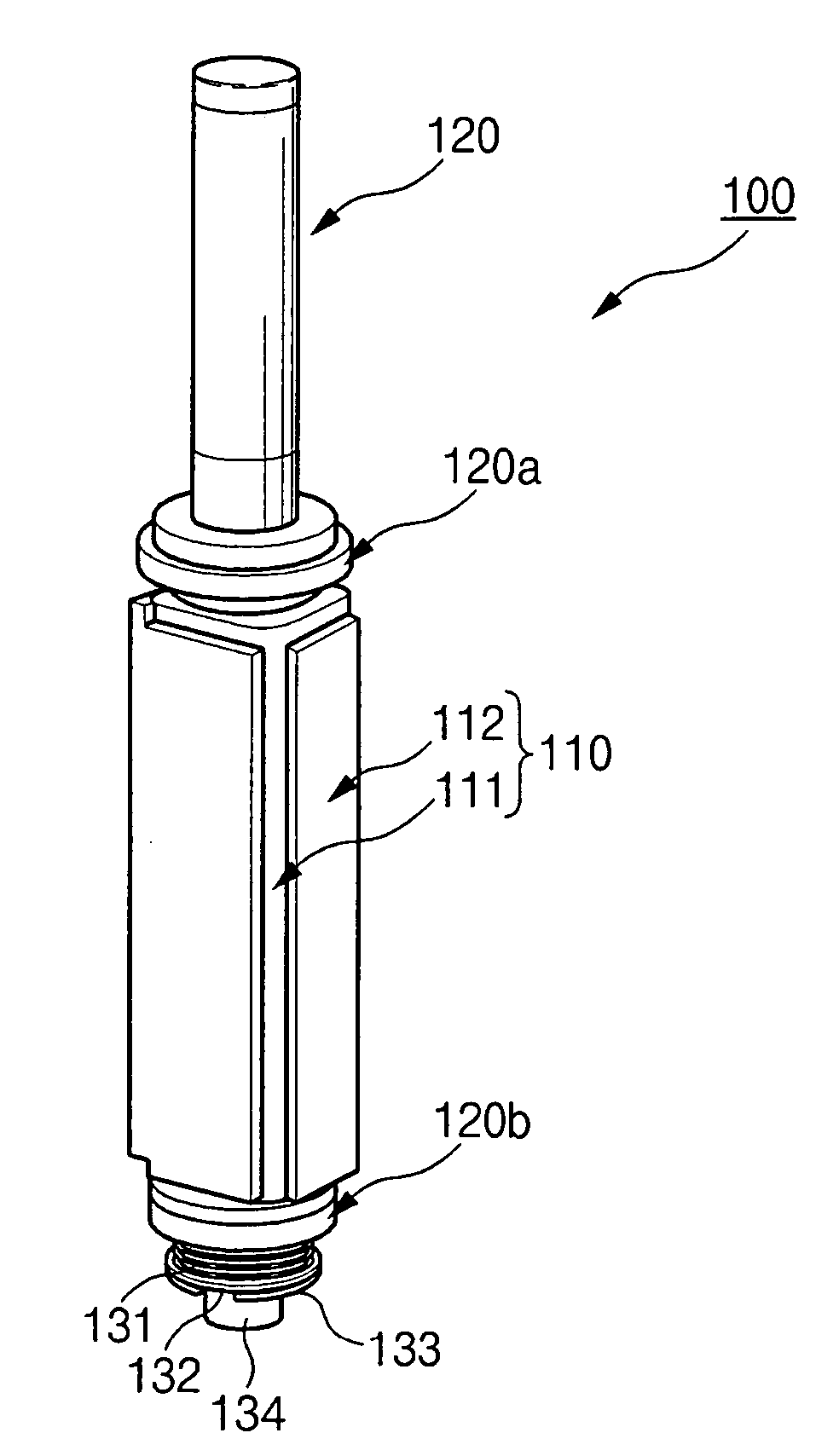
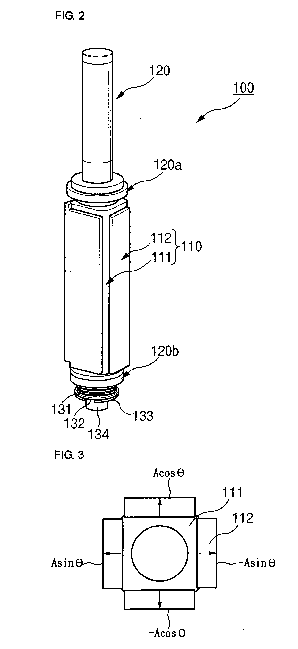
The present invention provides a stator and a ceramic tube type ultrasonic motor using the same. By using a ceramic material instead of a metallic material for the elastic body of the ultrasonic motor, abrasion caused by friction is minimized, constant operational characteristics are secured, and the number of module parts is reduced. The stator includes a tube-type elastic body that is formed of a ceramic material and a plurality of piezoelectric diaphragms that are attached on the outer peripheral surface of the elastic body in a longitudinal direction thereof and to which voltages having a phase difference are respectively applied. The ceramic material can be alumina or zirconia, and the outer peripheral surface of the elastic body can be coated with a conductive material to electrically connect the piezoelectric diaphragms. The ceramic tube type ultrasonic motor includes a stator and a rotor, and the elastic body flexurally vibrates due to the voltages applied to the piezoelectric diaphragms, resulting in the rotation of the rotor.

Problems solved by technology

In such a piezoelectric ultrasonic motor, however, characteristics thereof are degraded by the friction with a rotor, and a driving frequency changes.
As described above, however, the housing can be worn down because the metallic elastic body is formed in a tube shape.
Further, when the tube is made of piezoelectric ceramic, there are difficulties in manufacturing, and a driving force is not effectively delivered to a rotor because of a low friction index and low mechanical strength of piezoelectric ceramic.
In this case, however, the above-described abrasion can still occur, because the metallic bodies serving as an elastic body of a stator are made of a metallic material such as stainless steel.

Method used


Image

  • Stator and ceramic tube type ultrasonic motor using the same
  • Stator and ceramic tube type ultrasonic motor using the same
  • Stator and ceramic tube type ultrasonic motor using the same

Examples


Embodiment Construction

[0027] Reference will now be made in detail to the embodiments of the present general inventive concept, examples of which are illustrated in the accompanying drawings, wherein like reference numerals refer to the like elements throughout. The embodiments are described below in order to explain the present general inventive concept by referring to the figures.

[0028] Hereinafter, preferred embodiments of the present invention will be described in detail with reference to the accompanying drawings.

[0029] Stator

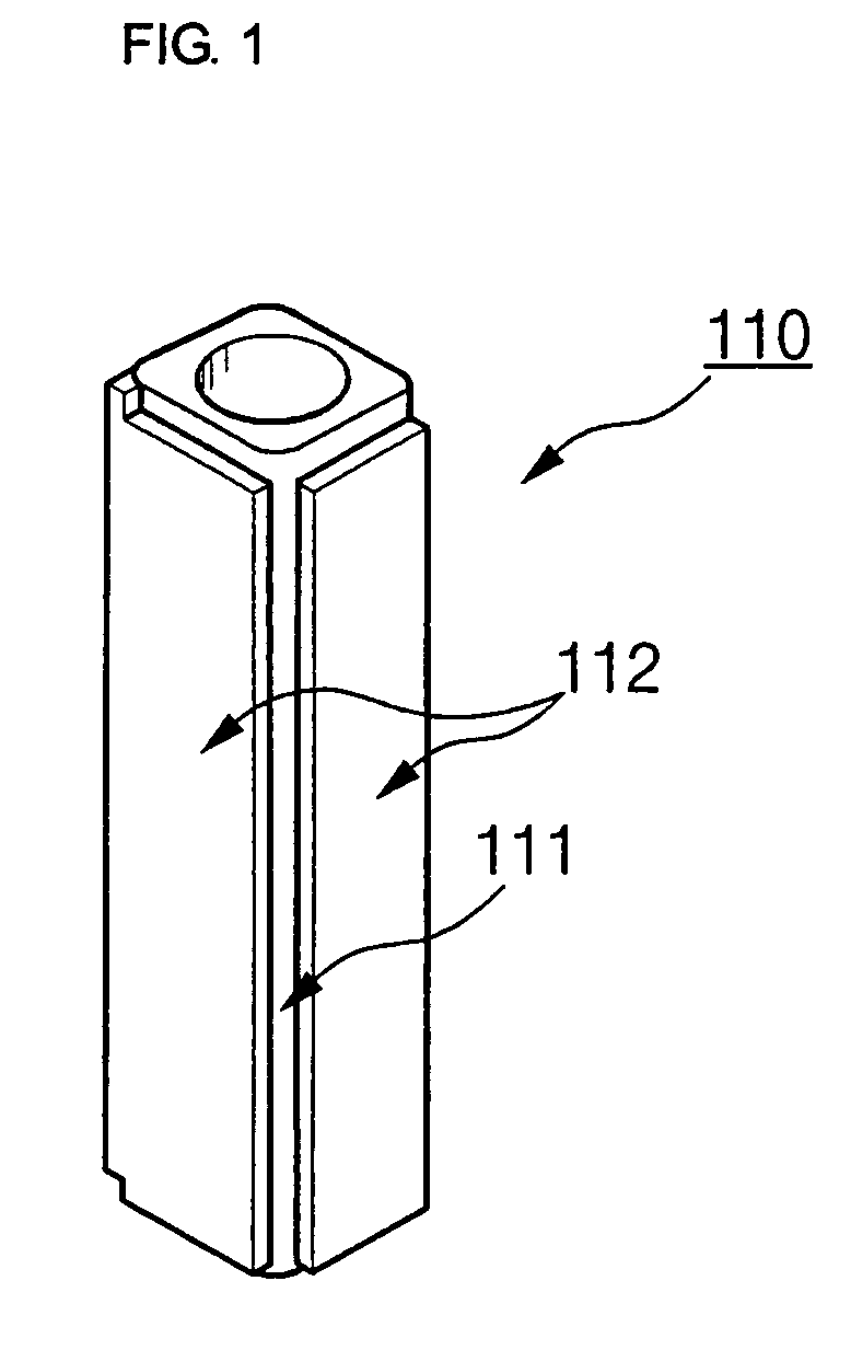
[0030]FIG. 1 is a diagram illustrating a stator 110 used for a ceramic tube type ultrasonic motor 100 according to the present invention.

[0031] As shown in FIG. 1, the stator 110 of the invention includes a tube-type elastic body 111 made of a ceramic material and a plurality of piezoelectric diaphragms 112 which are attached on the outer peripheral surface of the elastic body 111 and to which voltages having a phase difference are respectively applied.

[0032] The elastic bo...


PUM


Abstract

The present invention relates to a ceramic tube type ultrasonic motor having a stator including a tube-type elastic body that is formed of a ceramic material; and a plurality of piezoelectric diaphragms that are attached on the outer peripheral surface of the elastic body in a longitudinal direction thereof and to which voltages having a phase difference are respectively applied and a rotor that is rotated by the friction with the elastic body flexurally vibrating due to the voltages applied to the plurality of piezoelectric diaphragms.

Description

CROSS-REFERENCE TO RELATED APPLICATIONS [0001] The application claims the benefit of Korea Patent Application No. 2005-0072091 filed with the Korea Intellectual Property Office on Aug. 8, 2005, the disclosure of which is incorporated herein by reference. BACKGROUND OF THE INVENTION [0002] 1. Field of the Invention [0003] The present invention relates to a stator and a ceramic tube type ultrasonic motor using the same. In the stator, an elastic body producing friction with a rotor is formed of a ceramic material having excellent abrasion resistance instead of a metallic material, thereby minimizing abrasion caused by the friction. [0004] 2. Description of the Related Art [0005] As the information technology rapidly develops, electronic and optical apparatuses are required, which are faster and more precise. Particularly, the market of portable mobile application products is expanding every year. Among them, mobile phones having a camera mounted thereon tend to adopt a function of dig...

Claims


Application Information

Patent Timeline
Patent Type & Authority Applications(United States)
IPC IPC(8): H01L41/00H02N2/00
CPCH02N2/106H02N2/0015H02N2/00H02N2/02
Inventor LEE, DONGKOC, BURHANETTINKANG, BYUNG
Owner SAMSUNG ELECTRO MECHANICS CO LTD
Learn More