Driving method of display device using organic self-luminous element and driving circuit of same
- Summary
- Abstract
- Description
- Claims
- Application Information
AI Technical Summary
Benefits of technology
Problems solved by technology
Method used
Image
Examples
first embodiment
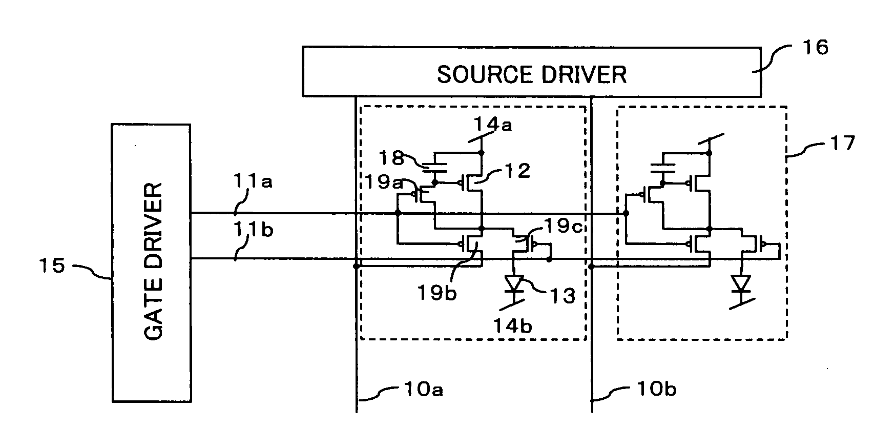
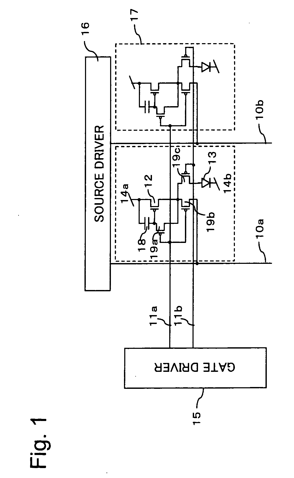
[0162] First, a first system for increasing a writing current N-fold will be explained in a first embodiment. Components identical with those explained above are denoted by the identical reference numerals and signal. Detailed explanations of the components are omitted.
[0163] An example of a structure of an output stage of a current output type source driver is shown in FIG. 8.
[0164] In the source driver that performs current output, as shown in FIG. 8, current sources 82 (which means 82a, 82b, and the like in FIG. 8) are prepared by the number of bits as the structure of the output stage. Outputs of the respective current sources 82 are varied such that the respective current sources 82 output electric currents corresponding to weights of the bits.
[0165] As shown in FIG. 8, in a least significant bit, a current source 82a with a current output of I is provided. In higher order bits, current sources with current outputs twice as large as that of the preceding current sources are ...
second embodiment
[0184] A second system for increasing a writing current N-fold will be explained in a second embodiment. Components identical with those explained above are denoted by the identical reference numerals and signs. Detailed explanations of the components are omitted.
[0185]FIG. 14 is a diagram showing a relation between a reference current generating unit and output stages of respective colors. As shown in FIG. 14, MOS transistors are used as transistors.
[0186] In a current output type driver, a current output stage has a structure shown in FIG. 14. In this case, a gradation depends on the number of transistors connected to an output. An electric current per one gradation depends on a current value flowing to resistors 144 (which mean resistors denoted by 144a, 144b, and 144c in FIG. 14). This is because an electric current flowing to the resistors 144 is transmitted to respective current sources for gradation display of respective outputs by a current mirror constitution. A current v...
third embodiment
[0227] A third embodiment of the present invention will be explained.
[0228] In the third embodiment, a case in which luminance of a display screen is changed according to command control using the source driver in the second embodiment will be explained.
[0229] If the source driver in the second embodiment of the present invention is used, it is possible to change a current value per one gradation at arbitrary timing. In the past, a light emission period is reduced in association with an increase in a current value. However, if the light emission period is fixed, it is possible to increase luminance. Since a current value can be changed by the electronic volume 143d in the structure shown in FIG. 21, it is possible to change luminance according to command control.
[0230]FIG. 26 is a diagram showing a digital camera including the display device according to the second embodiment of the present invention. A digital camera 261 includes a photographing unit 262, a shutter switch 263, a...
PUM
 Abstract
Description
Claims
Application Information
 - R&D
- Intellectual Property
- Life Sciences
- Materials
- Tech Scout
- Unparalleled Data Quality
- Higher Quality Content
- 60% Fewer Hallucinations
Browse by: Latest US Patents, China's latest patents, Technical Efficacy Thesaurus, Application Domain, Technology Topic, Popular Technical Reports.
© 2025 PatSnap. All rights reserved.Legal|Privacy policy|Modern Slavery Act Transparency Statement|Sitemap|About US| Contact US: help@patsnap.com


