
Balanced MEMS switch for next generation communication systems

a communication system and switch technology, applied in the field of microelectromechanical system switch, can solve the problems of higher actuation voltage, more sensitive to environmental temperature change, and inferior stress relief mechanism of such a armature, so as to reduce the probability of the switch sticking and reduce the required mechanical force

Inactive Publication Date: 2007-02-08
WIRELESS MEMS
View PDF4 Cites 5 Cited by
  • Summary
  • Abstract
  • Description
  • Claims
  • Application Information

AI Technical Summary

Benefits of technology

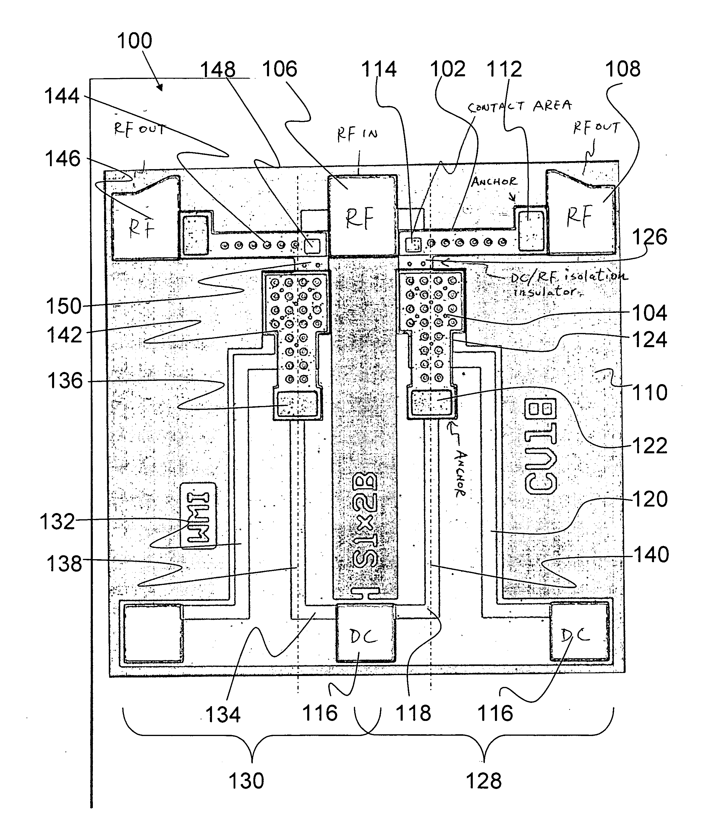
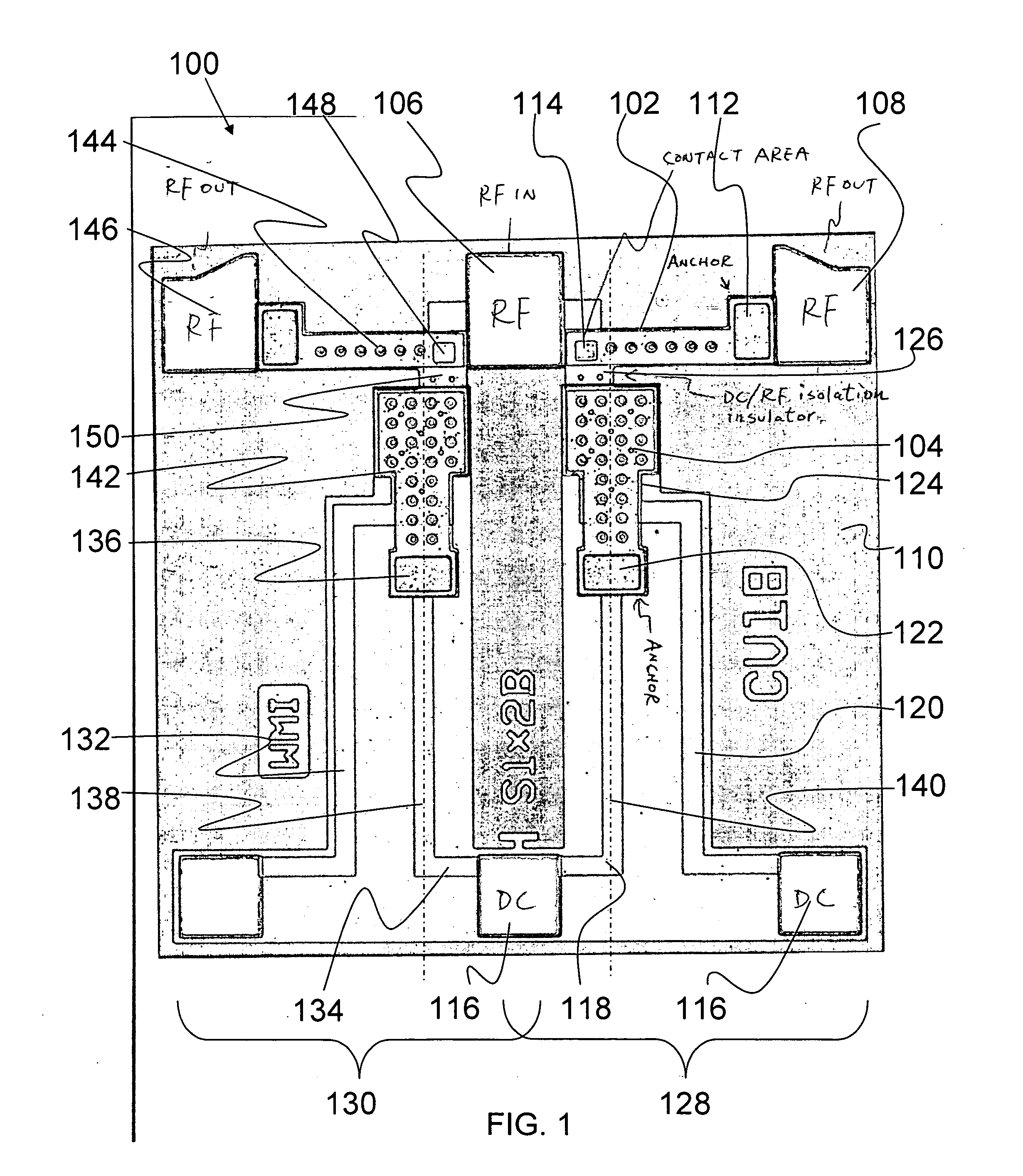
[0011] In yet another aspect, the bias armature is formed such that it is substantially parallel to the RF armature. The armatures can be closer together in this configuration. Thus, the mechanism for lifting the switch when the switch is in a closed position tends to be more robust and faster.
[0012] In yet another aspect, the bias armature is formed such that it is substantially parallel to the RF armature, and the DC / RF isolation insulator is formed such that it is substantially perpendicular to both the bias armature and the RF armature. Again, the armatures can be closer together in this configuration, and the mechanism for lifting the switch when the switch is in a closed position tends to be more robust and faster; in particular, with the DC / RF isolation insulator perpendicular to the bias armature and RF armature, the arrangement occupies the smallest area of the substrate if the sizes of the RF armature and bias armature are fixed.
[0013] In yet another aspect, the bias armature is formed such that it is substantially perpendicular to the RF armature. This configuration greatly reduces the probability of the switch sticking in the closed position; effectively, the contact tends to lift from one corner, rather than trying to lift the whole contact at once, which greatly reduces the required mechanical force.

Problems solved by technology

However, the stress relief mechanism of such an armature may be inferior due to its rigidness.
As a result, it may be more sensitive to an environmental temperature change and has a higher actuation voltage than other designs, unless some a design technique such as a meander is adopted.
In addition, the two contact areas may not reach the optimal contact condition simultaneously which can cause further contact problems.

Method used


Image

  • Balanced MEMS switch for next generation communication systems
  • Balanced MEMS switch for next generation communication systems

Examples


Embodiment Construction

[0023] The present invention relates to a micro-electro-mechanical system (MEMS) switch, and more particularly to a balanced MEMS switch having a bias armature and an RF armature, each having their own anchors and being positioned substantially perpendicular to each other. The following description is presented to enable one of ordinary skill in the art to make and use the invention and to incorporate it in the context of particular applications. Various modifications, as well as a variety of uses in different applications will be readily apparent to those skilled in the art, and the general principles defined herein may be applied to a wide range of embodiments. Thus, the present invention is not intended to be limited to the embodiments presented, but is to be accorded the widest scope consistent with the principles and novel features disclosed herein.

[0024] In the following detailed description, numerous specific details are set forth in order to provide a more thorough understa...


PUM


Abstract

A micro-electro-mechanical system (MEMS) switch is described. The MEMS switch includes both RF-input and output transmission lines formed on a substrate. An RF armature is anchored to the substrate and is electrically connected with the RF-output transmission line. A contact is electrically connected with the RF-input transmission line. Both bias-input and output signal lines are formed on the substrate. A bias armature is anchored to the substrate and is electrically connected with the bias-input signal line. A DC / RF isolation insulator connects the bias armature with the RF armature. When a charge is introduced to the bias-input signal line, the bias armature is forced toward the bias-output signal line, thereby forcing the RF armature to connect with the contact and form an electrical circuit between the RF-input transmission line and the RF-output transmission line.

Description

PRIORITY CLAIM [0001] The present application is a non-provisional utility patent application, claiming the benefit of priority of U.S. Provisional Patent Application No. 60 / 705,879, filed Aug. 4, 2005, titled “A BALANCED MEMS SWITCH FOR NEXT GENERATION COMMUNICATION SYSTEMS.”BACKGROUND OF THE INVENTION [0002] (1) Field of Invention [0003] The present invention relates to a micro-electro-mechanical system (MEMS) switch, and more particularly to a balanced MEMS switch having a bias armature and an RF armature, each having their own anchors and being positioned substantially perpendicular to each other. [0004] (2) Description of Related Art [0005] Micro-electro-mechanical system (MEMS) switches have long been known in the art. MEMS have been formed in a myriad of designs, including an armature design. The armature design often includes an armature affixed to two anchors at both ends of the armature, with the ends separated by 180 degrees. Such an armature design tends to have an impro...

Claims


Application Information

Patent Timeline
Patent Type & Authority Applications(United States)
IPC IPC(8): H01H53/00
CPCH01H59/0009
Inventor CHOU, CHIA-SHING
Owner WIRELESS MEMS
Learn More