Optical recording medium, manufacturing method thereof, method for recording data on optical recording medium, and data reproduction method

a technology of optical recording medium and manufacturing method, which is applied in the direction of optical recording/reproducing/erasing methods, instruments, and the like, can solve the problems of deterioration of the light transmitting layer, difficult to form various function layers such as recording layers in the next-generation optical recording medium, and difficulty in further shortening a wavelength. , to achieve the effect of good signal characteristics, good signal characteristics, and excellent characteristics

Inactive Publication Date: 2007-02-08
TDK CORPARATION
View PDF6 Cites 65 Cited by
  • Summary
  • Abstract
  • Description
  • Claims
  • Application Information

AI Technical Summary

Benefits of technology

[0030] According to the present embodiment, because the groove is set relatively deep on the substrate, the good signal characteristics can be obtained in carrying out the super-resolution recording and the super-resolution reading. In addition, when the groove is set relatively narrow on the substrate, the better signal characteristics can be obtained.
[0031] In particular, in the optical recording medium according to the present embodiment, since the laser beam whose wavelength is below about 635 nm and the objective lens whose numerical aperture is in excess of about 0.6 are employed, the super-resolution recording and the super-reso

Problems solved by technology

Therefore, unlike the existing optical recording medium such as CD, DVD, or the like, it is difficult to form various function layers such as the recording layer, and the like on the light transmissible substrate in the next-generation optical recording medium.
However, when a wavelength of the laser beam is reduced further, absorption of the laser beam in the light transmitting layer is increased suddenly and also a long-term

Method used


Image

  • Optical recording medium, manufacturing method thereof, method for recording data on optical recording medium, and data reproduction method
  • Optical recording medium, manufacturing method thereof, method for recording data on optical recording medium, and data reproduction method
  • Optical recording medium, manufacturing method thereof, method for recording data on optical recording medium, and data reproduction method

Examples


example 1

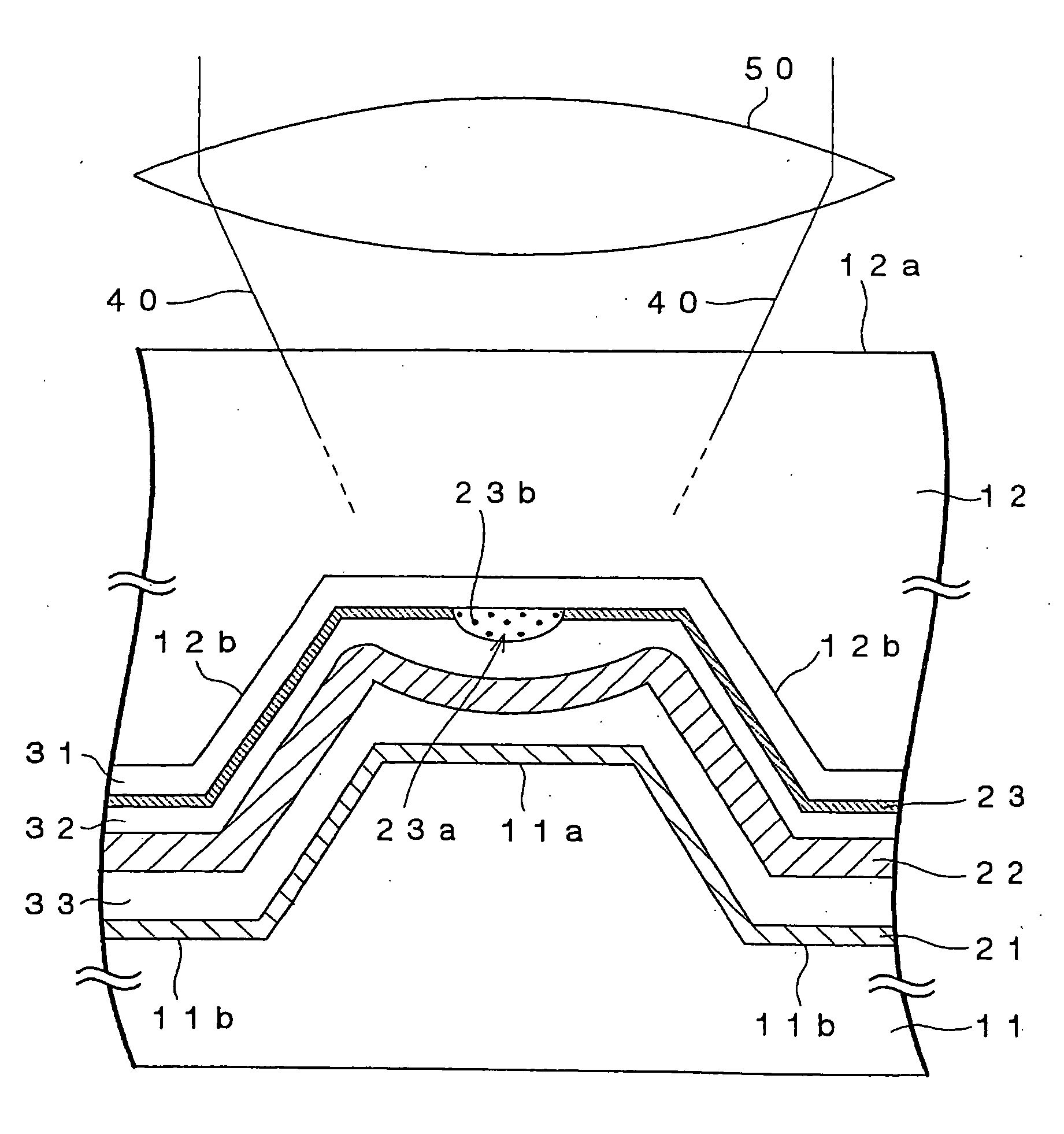
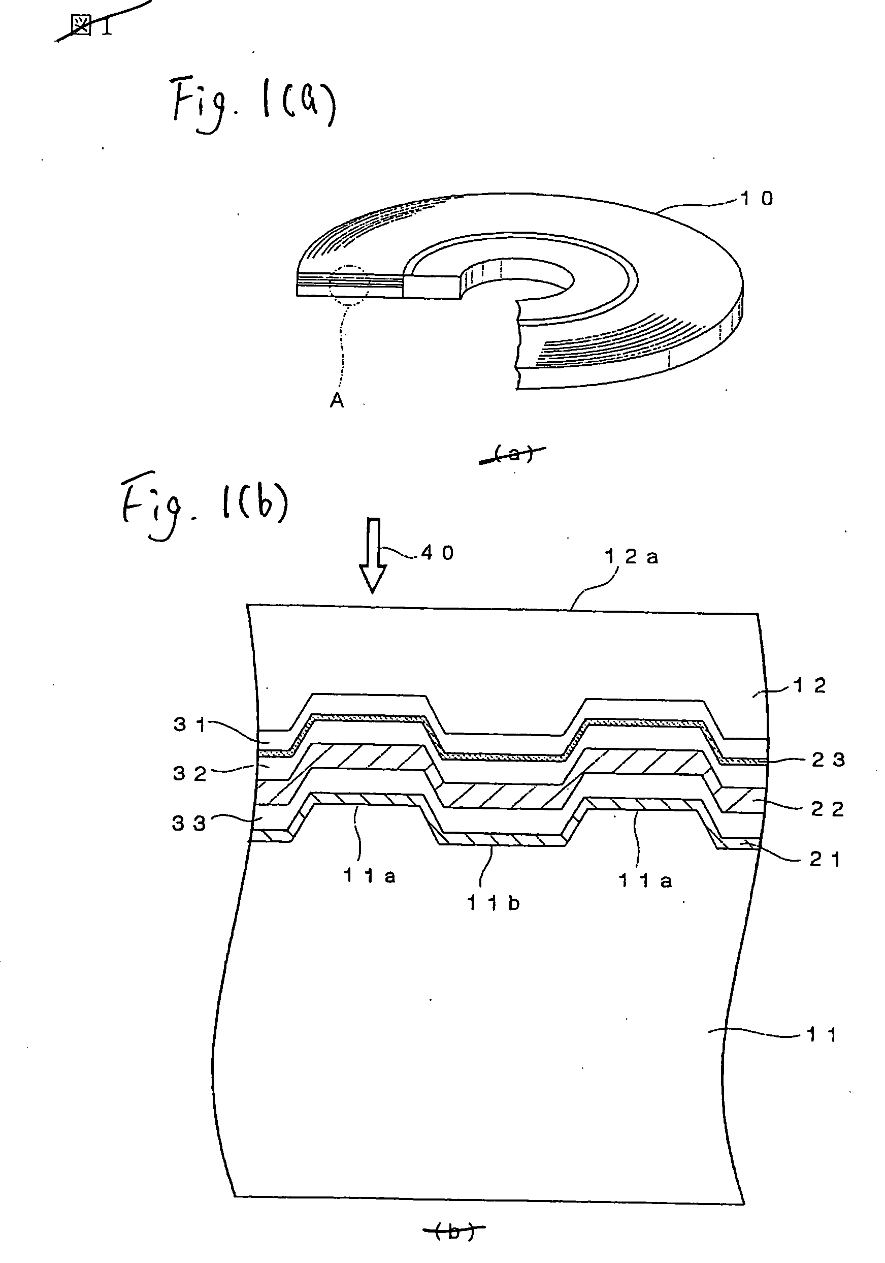
[0118] Samples of the optical recording medium having the same structure as the optical recording medium 10 shown in FIG. 1 were manufactured by the following method.

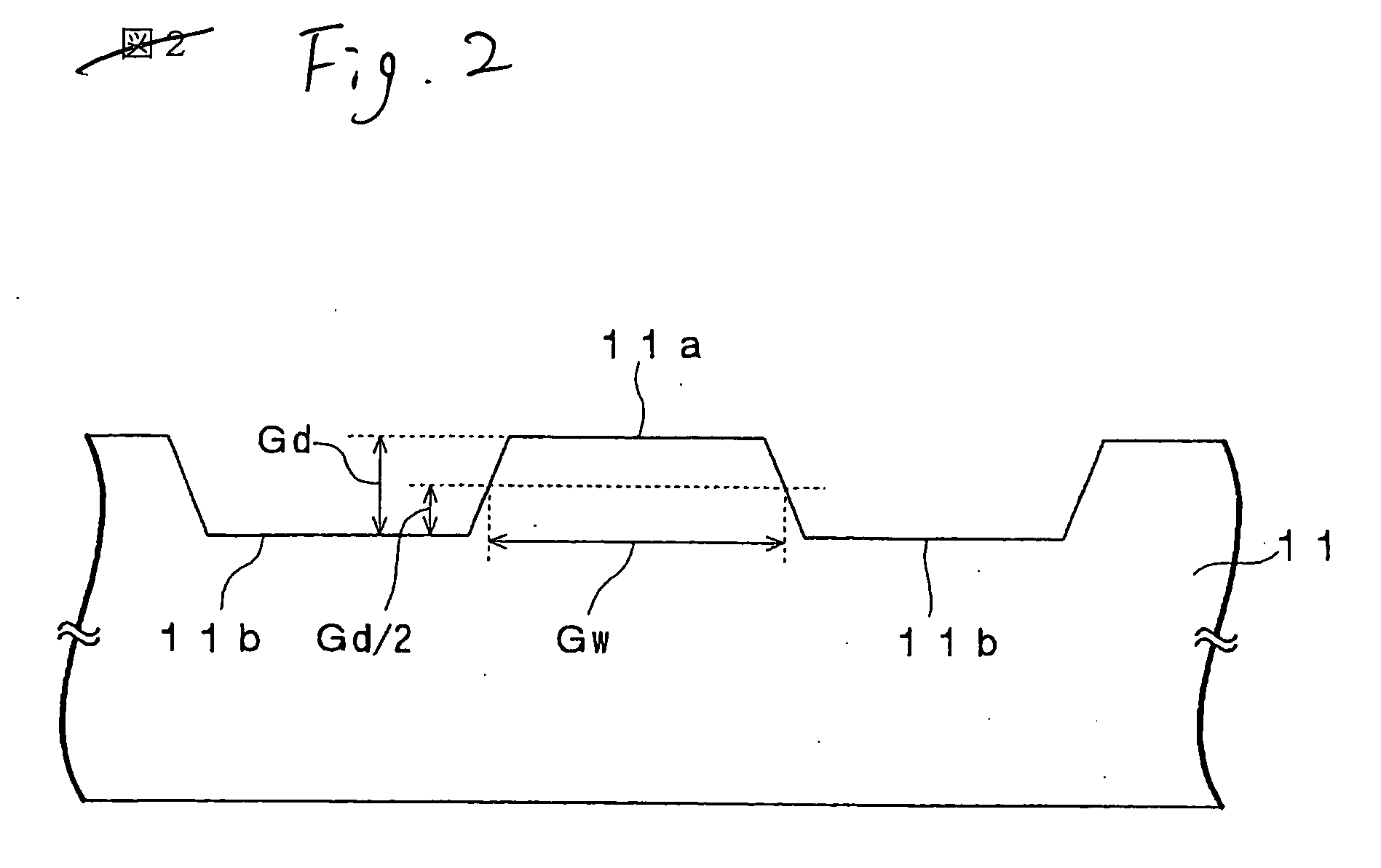
[0119] First, the disc-like supporting substrate 11 made of polycarbonate, which has a thickness of about 1.1 mm and a diameter of about 120 mm and on the surface of which the groove 11a and the land 11b are formed, was manufactured by the injection molding method. A depth Gd of the groove 11a was set to about 41 nm, and a width Gw of the groove 11a was set to about 169 nm. A track pitch was set to about 320 nm.

[0120] Then, the supporting substrate 11 was loaded in the sputtering equipment. Then, the reflecting layer 21 made substantially of platinum (Pt) and having a thickness of about 20 nm, the dielectric layer 33 made substantially of a mixture of ZnS and SiO2 (mole ratio=about 80:20) and having a thickness of about 100 nm, the light absorbing layer 22 made of the phase change material represented substantially by...

example 2

[0124] A sample of the optical recording medium according to Example 2 was manufactured by the similar way to the sample of the optical recording medium according to Example 1, except that the substrate on which the width Gw of the groove 11a is set to about 181 nm was used as the supporting substrate 11.

example 3

[0125] A sample of the optical recording medium according to Example 3 was manufactured by the similar way to the sample of the optical recording medium according to Example 1, except that the substrate on which the width Gw of the groove 11a is set to about 197 nm was used as the supporting substrate 11.


PUM


Abstract

An optical recording medium 10 according to the present invention includes a supporting substrate 11 on which a groove 11a is formed, a light transmitting layer 12, a noble metal oxide layer 23 provided between the supporting substrate 11 and the light transmitting layer 12, wherein a depth of the groove 11a is set in excess of λ/8 n but 60 nm or less, where n is a refractive index of the light transmitting layer 12 with respect to a light whose wavelength is λ. Thus, the good signal characteristics, especially a push-pull signal with an enough amplitude, can be obtained when the super-resolution recording and super-resolution reading are carried out by irradiating the laser beam onto the noble metal oxide layer 23. Also, since the depth of the groove is set to 60 nm or less, a grave difficulty never arises in producing a stamper used to manufacture the substrate.

Description

TECHNICAL FIELD [0001] The present invention relates to an optical recording medium and a method of manufacturing the same and, more particularly, an optical recording medium of the type that a recording mark is formed by released gas and a method of manufacturing the same. Also, the present invention relates to a data recording method and a data reading method for an optical recording medium and, more particularly, a data recording method and a data reading method for an optical recording medium of the type that a recording mark is formed by released gas. BACKGROUND ART [0002] As the recording medium for recording the large-capacity digital data, the optical recording medium as typified by a CD (Compact Disc) or a DVD (Digital Versatile Disc) is widely used in recent years. [0003] Out of the CDs, the type that can neither add the data nor rewrite the data (CD-ROM) has such a structure that a reflecting layer and a protection layer are stacked on a light tranmissive substrate having...

Claims


Application Information

Patent Timeline
IPC IPC(8): G11B3/70G11B7/24G11B7/004G11B7/0045G11B7/007G11B7/09G11B7/24047G11B7/24056G11B7/24062G11B7/24079G11B7/24085G11B7/243G11B7/2433G11B7/26
CPCG11B7/00452G11B7/24079G11B7/24065G11B7/0901G11B7/257G11B7/004
Inventor KIKUAWA, TAKASHIFUKUZAWA, NARUTOSHIKOBAYASHI, TATSUHIRO
Owner TDK CORPARATION
Why Eureka
Try Eureka