Optical recording medium and method for producing the same

a recording medium and optical technology, applied in the field of optical recording mediums, can solve the problems of reducing the injection pressure of resin materials, and reducing the injection speed of resin materials, etc., to achieve excellent signal characteristics, sufficient rotation performance, and enhanced rigidity of substrates

Inactive Publication Date: 2003-07-22
SONY CORP
View PDF7 Cites 0 Cited by
  • Summary
  • Abstract
  • Description
  • Claims
  • Application Information

AI Technical Summary

Benefits of technology

Focal depth {character pullout}.varies.e / (NA).sup.2
SKEW allowed value {character pullout}.varies.e / (NA).sup.3
An object of this invention is to provide an optical recording medium in which there is no deformation such as curvature or concave portion of the disc substrate, having sufficient rotation performance, and which can sufficiently cope with realization of high recording density and a method of manufacturing such an optical recording medium.
In the optical recording medium according to this invention thus constituted, rigidity of the substrate is enhanced by the intermediate layer including the rigidity rendering material, and the uneven pattern is formed on the surface layer formed on the intermediate layer. For this reason, in the optical recording medium it is not possible for the rigidity rendering material to face the surface where the uneven pattern is formed. Thus, the optical recording medium exhibits excellent signal characteristics and has excellent rigidity.
In the method of manufacturing the optical recording medium according to this invention thus featured, there is employed such an approach to transfer a reversed uneven pattern formed on the stamper onto the surface layer to integrate the surface layer and the intermediate layer including the rigidity rendering material to thereby form substrate. For this reason, in accordance with this technique, it is possible to manufacture a substrate having excellent rigidity and to transfer a reversed uneven pattern with high accuracy.
Further, it is preferable that the surface layer 9 of the substrate 2 is formed by resin having a percentage of water absorption of 0.3% or less. Furthermore, it is more preferable to form surface layer 9 by using resin having a percentage of water absorption of 0.1% or less. By forming the surface layer 9 by resin having percentage of water absorption of 0.3% or less, it impossible to prevent the surface layer 9 from absorbing moisture, etc. in air so that the optical disc is deformed. Thus, an optical disc 1 having less quantity of deformation can be formed. For example, even in the case where the curvature deformation angle is less than 0.4 degrees in the predetermined standard, the percentage of water absorption of resin is caused to be 0.3% or less, thereby making it possible to securely satisfy the above-mentioned standard.

Problems solved by technology

Further, since the disc substrate is formed by resin material, it is difficult to avoid contraction deformation particularly in the cooling process of the injection molding process.
For this reason, in the conventional injection molding process, in order to suppress, to the utmost, such contraction deformation or deformation of disc substrate by the above- described residual internal stress, complicated labors are required such as weakening the clamping pressure of the metal mold, lowering the injection speed of resin material and / or weakening the injection pressure of resin material.
In addition, in the conventional injection molding process, such deformation is produced, whereby concave (hollow) portion or swollen portion takes place at the outer circumferential portion of the disc substrate, or it becomes difficult to transfer, with good accuracy, reversed uneven patterns of stamper.
However, in the conventional injection molding process, there is the problem that the molecular weight of resin material is reduced so that mechanical characteristic such as rigidity, etc. of the disc substrate is degraded.
In addition, in the conventional injection molding process, there is the problem that metal mold temperature is increased so that thermal deformation takes place at the time of taking out the disc substrate, or the molding cycle is elongated.
However, in the case where such an optical disc is used, focal depth of the object lens becomes small, and spot diameter of the laser becomes small.
In addition at the time of manufacturing the thin substrate, the substrate is molded while being solidified resulting from a temperature difference between metal mold and resin.
Thus, orientation distortion becomes more conspicuous.
For example, in the case where thickness of the substrate is 0.4 mm or less, degradation of transfer characteristic, unevenness of double refraction and occurrence of curvature become conspicuous along with orientation distortion.
For this reason, in the case where the compound mold material is used, there is the problem that it is impossible to precisely transfer fine uneven patterns in order to manufacture substrate suitable for optical recording media which cope with high density recording.
For this reason, in the optical recording medium it is not possible for the rigidity rendering material to face the surface where the uneven pattern is formed.
Accordingly, it is sufficient that water absorption deformation is not taken into consideration even in all the preservation / use environments.

Method used


Image

  • Optical recording medium and method for producing the same
  • Optical recording medium and method for producing the same
  • Optical recording medium and method for producing the same

Examples


first embodiment

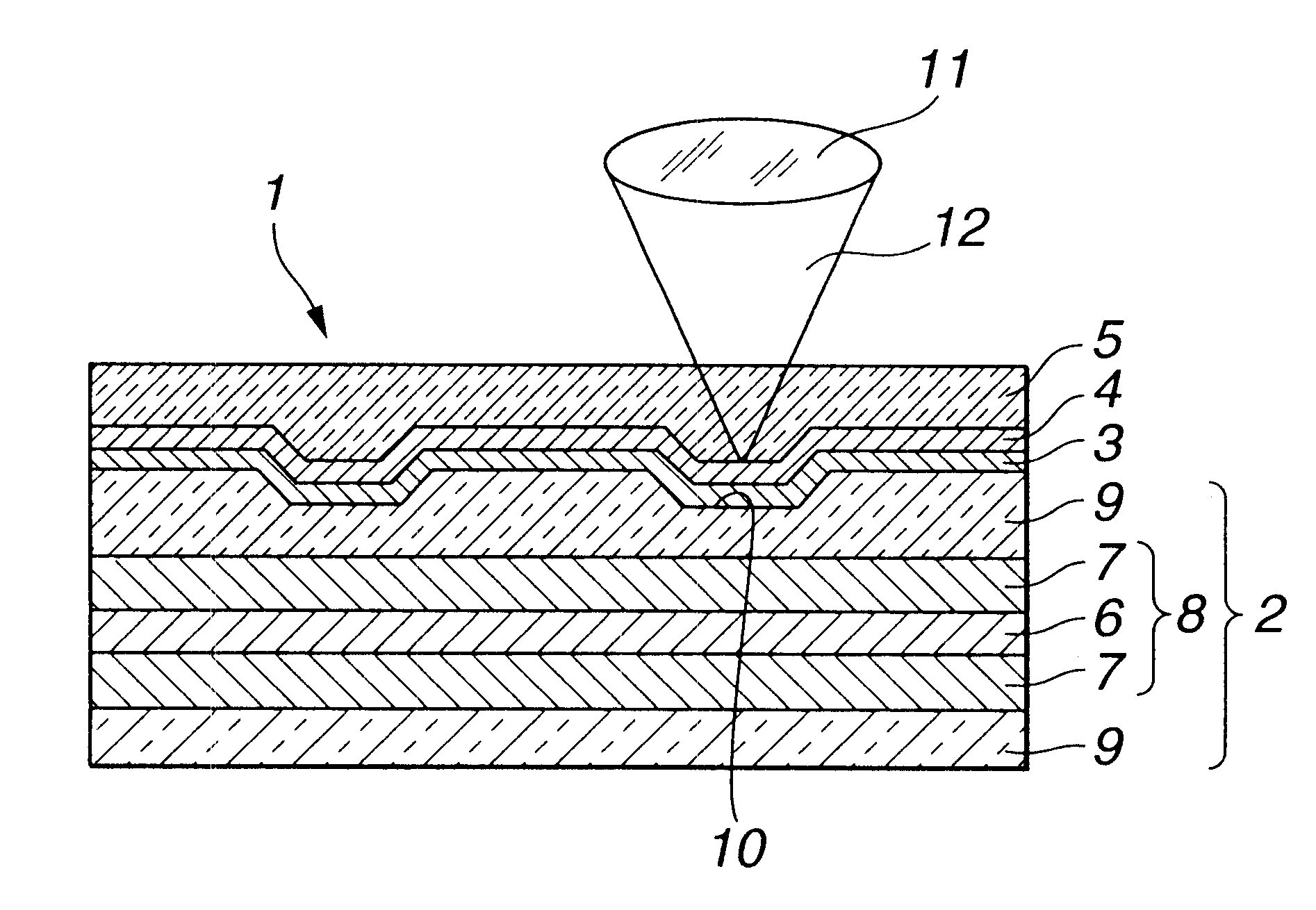
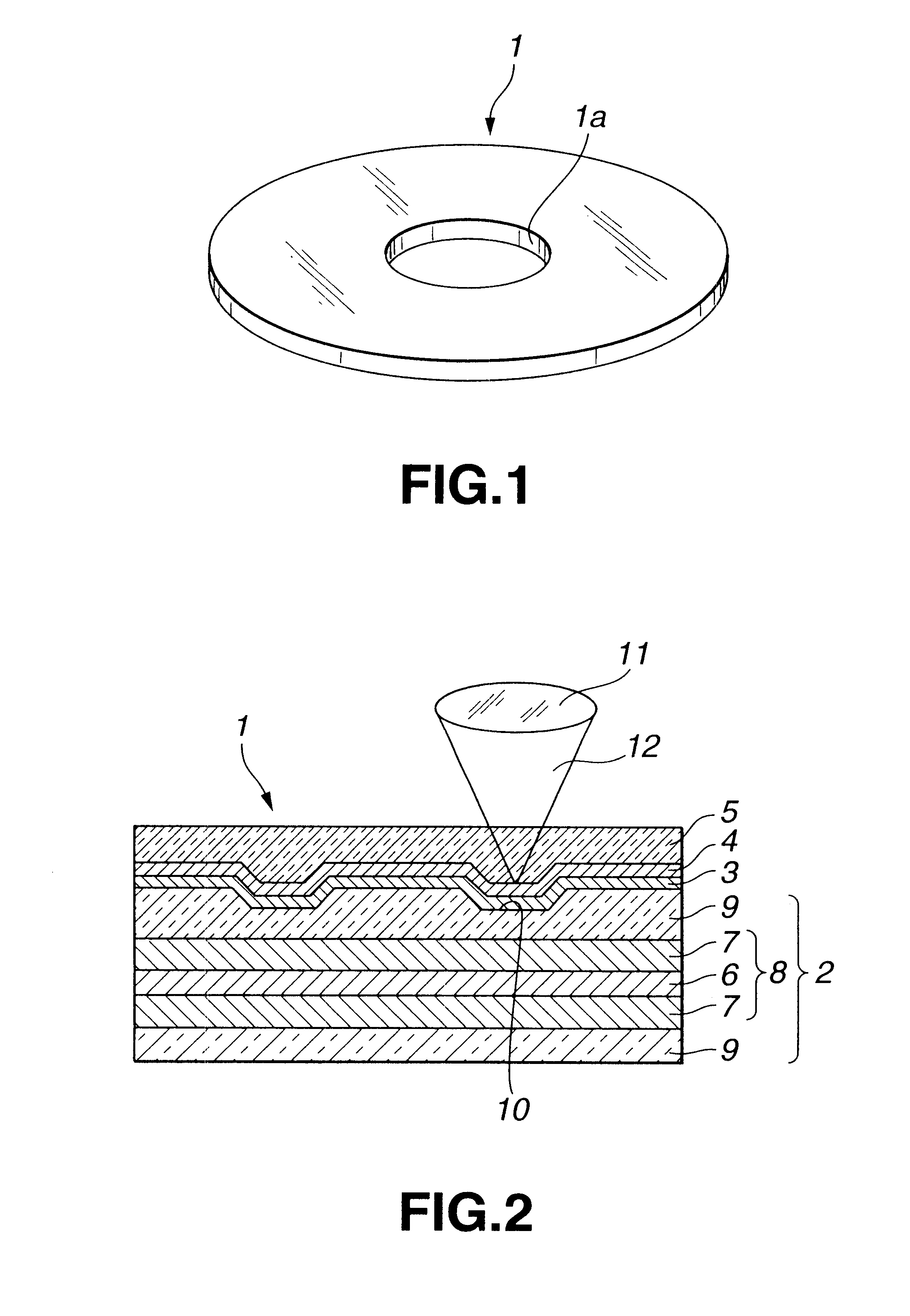
An optical disc as shown in FIG. 1 was manufactured. The surface layer, and the intermediate layer consisting of a core layer and fiber layer were prepared by using materials as described below.

Resin material: ZEONEX E-490(by Nihon Zeon Kabushiki Kaisha)

Glass transition temperature: 136.degree. C (Measurement method DSC)

Bending elastic modulus: 23,000 kgf / cm.sup.2 (ASTM D790)

Thermal deformation temperature: 122.degree. C (ASTM D648)

Percentage of water absorption: 0.01% or less (ASTM D570)

Refraction factor: 1.53 nd 25 (ASTM D542)

Specific gravity: 1.01 (ASTM D792)

Photoelasticity constant: 2 .times.10.sup.-13 cm.sup.2 / dyne

The surface layer was prepared by allowing ZEONEX E-490 to be in a form of thin plate a having thickness of 0.2 mm.

Resin material: ZEONR 1420 (by Nihon Zeon Kabushiki Kaisha)

Glass transition temperature: 136.degree. C

Bending elastic modulus: 22,000 kgf / cm.sup.2

Thermal deformation temperature: 136.degree. C

Percentage of water absorption: 0.01% or less

Refraction factor...

second embodiment

In the second embodiment, an optical disc as shown in FIG. 7 was manufactured. The surface layer and the intermediate layer were prepared by using materials as described below.

Resin material: polycarbonate ST-3000 (by Teijin Kasei Kabushiki Kaisha)

Glass transition temperature: 145.degree. C

Bending elastic modulus: 28,700 kgf / cm.sup.2

Thermal deformation temperature: 133.degree. C

Percentage of water absorption: 0.15% or less

Refraction factor: 1.585 nd 25

Specific gravity: 1.13

Photoelasticity constant: 45.times.10.sup.-13 cm.sup.2 / dyne

Polycarbonate ST-3000 was forced out so that its thickness was equal to 0.2 mm to allow the article to be in a sheet form to thereby prepare the surface layer.

Fiber material: Toreka texitile fabrics prepreg 2500 (By Toray kabushiki kaisha) (Material in which epoxy resin is impregnated into carbon fiber fabrics)

Warp / Weft: Flat fabrics of respective T300-3000 filaments

Resin percentage content: 40%

Thickness: 0.25 mm

The intermediate layer was put between a pa...

third embodiment

In the third embodiment, an optical disc as shown in FIG. 7 was manufactured. The surface layer and the intermediate layer were prepared by using materials as described below.

Resin material: ZEONEX E-490 (by Nihon ZEON Kabushiki kaisha)

Glass transition temperature: 136.degree. C (Measurement Method DSC)

Bending elastic modulus: 23,000 kgf / cm.sup.2 (ASTM D790)

Thermal deformation temperature: 122.degree. C (ASTM D648)

Percentage of water absorption: 0.01% or less (ASTM D570)

Refraction factor: 1.53 nd 25 (ASTM D542)

Specific gravity: 1.01 (ASTM D792)

Photoelasticity constant: 2.times.10.sup.-13 cm.sup.2 / dyne

ZEONEX E-490 was forced out so that the thickness was equal to 0.2 mm to allow it to be in a sheet form to prepare surface layer.

Resin material: ZEONR 1600 (by Nihon Zeon Kabushiki Kaisha)

Glass transition temperature: 163.degree. C

Bending elastic modulus: 28,000 kgf / cm.sup.2

Thermal deformation temperature: 141.degree. C

Percentage of water absorption: 0.01% or less

Refraction factor: 1.5...


PUM

PropertyMeasurementUnit
thicknessaaaaaaaaaa
thicknessaaaaaaaaaa
thicknessaaaaaaaaaa

Abstract

An optical recording medium comprises a substrate having one principal surface on which uneven pattern is formed, and adapted so that light is irradiated onto the uneven pattern and recording/reproduction of recording signals are carried out by the irradiated light. The substrate includes an intermediate layer including rigidity rendering material and a surface layer formed on at least one principal surface of the intermediate layer and adapted so that the uneven pattern is formed. As the rigidity rendering material, there are used granulated filling material, plate-shaped filling material and fiber material. In manufacturing such an optical recording medium, the surface layer is disposed in a manner to oppose stamper where reversed uneven pattern is formed and the intermediate layer including rigidity rendering material is stacked on the surface layer. By heating and pressure-fitting such stamper, surface layer and intermediate layer, the surface layer and the intermediate layer are integrated and the reversed uneven pattern is transferred onto the surface layer.

Description

DESCRIPTION1. Technical FieldThis invention relates to an optical recording medium provided with a substrate having an uneven pattern formed on at least one principal surface and a method of manufacturing such an optical recording medium.2. Background ArtOptical recording media are recording media used with respect to recording / reproducing apparatus and adapted so that recording and / or reproduction (hereinafter referred to as recording / reproduction) of various information, e.g., audio (sound) information, picture information or character information, etc. is carried out by such recording / reproduction apparatus (unit). Optical recording media generally have a disc shape. There are various kinds of optical discs, including, for example, an optical disc in which recording signals are written in advance by physical uneven shapes called pits, a phase change type optical disc in which recording signals are written by making use of the phase change of a signal recording layer, and magneto-...

Claims


Application Information

Patent Timeline
Patent Type & Authority Patents(United States)
IPC IPC(8): B29D17/00G11B11/00G11B7/24G11B11/105G11B7/257G11B7/26G11B7/24047G11B7/2405G11B7/2542
CPCB29D17/005G11B7/24G11B7/252G11B7/2533G11B7/26G11B11/10584G11B7/2433G11B7/2534Y10T428/2913G11B7/256G11B11/10582Y10T428/21Y10T428/2911G11B7/2542
Inventor ARAKAWA, NOBUYUKI
Owner SONY CORP
Why Eureka
Try Eureka