
Process and apparatus for producing magnetic recording medium

a technology of magnetic recording medium and processing equipment, which is applied in the direction of vacuum evaporation coating, coating, coating carrier support, etc., can solve the problems of one-tenth as much recording density, limited use of hard disks as removable media, and inferior high density recording characteristics of flexible disks and magnetic tapes, so as to reduce defects on magnetic recording medium, excellent production suitability, and prevent deformation

Inactive Publication Date: 2006-07-20
FUJIFILM CORP +1
View PDF0 Cites 67 Cited by
  • Summary
  • Abstract
  • Description
  • Claims
  • Application Information

AI Technical Summary

Benefits of technology

The present invention provides a process and apparatus for producing a magnetic recording medium with reduced defects and improved production efficiency. The process involves unrolling a flexible polymer substrate, forming a magnetic layer on at least one side of the substrate, and taking up the substrate on a take-up roll. The film forming chamber is maintained in a vacuum state to prevent deformation of the substrate and improve the quality of the magnetic recording medium. The invention also provides a vacuum separator for selectably connecting and closing the film forming chamber and the roll chamber containing the feed roll and take-up roll. The process can produce a magnetic recording medium with high recording density, large capacity, and high reliability at low cost.

Problems solved by technology

However, the hard disks have rigid substrates and the heads are only at a very short distance from the disks as described above, so that use of the hard disks as removable media like flexible disks or rewritable optical disks is limited on account of high possibility of troubles due to crashes or dust entrapment during rotation.
Compared with hard disks comprising magnetic layers formed by sputtering, such flexible disks and magnetic tapes are inferior in high density recording characteristics, achieving at the most, only one-tenth as much recording density as with the hard disks.
One problem encountered in the production of the magnetic recording media using the long substrates is that flakes are deposited on a vacuum chamber in the vacuum film formation, and are peeled off to adhere to the magnetic recording media to cause defects.
When the vacuum chamber is opened to atmospheric pressure, the surface of the film deposited inside the vacuum chamber adsorbs moisture and oxygen in the air and thereby suffers from physicochemical changes.
As a result of repetition of evacuation and opening to atmospheric pressure, the film attached inside the vacuum chamber tends to be easily peeled off and adhere to the magnetic recording medium as defects.
Thus, such apparatuses need cleaning of the vacuum chamber each time production of a long magnetic material finishes or at a certain production interval, resulting in poor productivity.
Though such diamond-like carbon films exhibit desired characteristics on the media, a film deposited on a vacuum chamber is easily peeled off and causes defects because of its large film stress.
Also from this viewpoint, venting the vacuum chamber to the atmosphere is unfavorable.
The impurity gases in the magnetic layer forming system adversely affect the magnetic characteristics of the resulting magnetic recording medium, and thus it is unfavorable to form the magnetic layer and the protective layer in the film forming chambers using the same vacuum system.
Not only production costs but also defects are remarkably increased due to the increase of the number of passes.
However, in the methods disclosed in JP-B-61-36862 and JP-A-9-230538, it is difficult to secure a high vacuum degree constantly and an impurity gas in the air is inevitably incorporated into the vacuum film forming chamber.
Therefore, it is very difficult to stably produce the high density magnetic recording media by the methods.
Furthermore, in the methods, the flexible polymer substrate is conveyed through a vacuum separation and highly pressed by a seal roll therein, whereby the magnetic layer is apt to suffer from scratches or pressure marks, making it difficult to produce a highly reliable magnetic recording medium.
Further, in the case of using a CoPtCr-based magnetic layer and a Cr alloy underlayer, which are commonly used in hard disks, the substrate temperature has to be 200° C. or higher and thereby the polymer film is thermally damaged and unpractical.
Though a proposal has been made on using a highly heat-resistant film of a polyimide or an aromatic polyamide as the polymer film, it is difficult to put such a heat-resistant film into practical use because of the large cost.
However, the methods are insufficient for using a substrate of polyethylene terephthalate, polyethylene naphthalate, etc. with a low glass transition temperature and for reducing the substrate deformation to the level required for high density recording.
Additionally, the optical disks have lower surface recording densities and lower data transfer rates as compared with the magnetic disks, and thus cannot have sufficient performance for use as rewritable, large-capacity recording media,

Method used


Image

  • Process and apparatus for producing magnetic recording medium
  • Process and apparatus for producing magnetic recording medium
  • Process and apparatus for producing magnetic recording medium

Examples


example 1

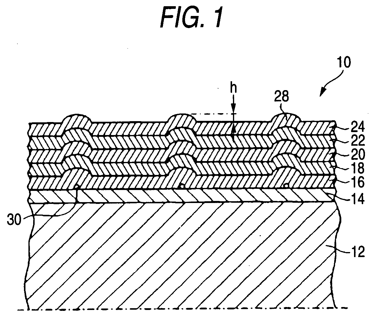
[0203] An undercoating liquid containing 3-glycidoxypropyltrimethoxysilane, phenyltriethoxysilane, hydrochloric acid, aluminum acetylacetonate, and ethanol was applied to a polyethylene naphtbalate film having a thickness of 63 μm, a surface roughness Ra of 1.4 nm, and a length of 300 m by gravure coating, and dried and hardened at 100° C., to form a 1.0-μm-thick undercoating layer 14 of a silicone resin. A coating liquid containing a silica sol having a particle size of 25 nm and the undercoating liquid was applied to the undercoating layer 14 by gravure coating, to form projections having a height of 15 nm on the undercoating layer 14 at a density of 10 projections / μm2. The undercoating layer 14 was formed on both sides of the substrate 12.

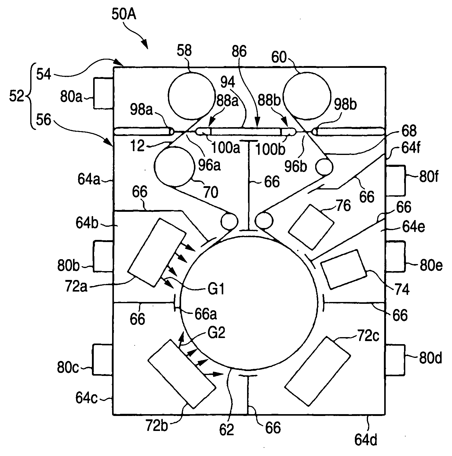
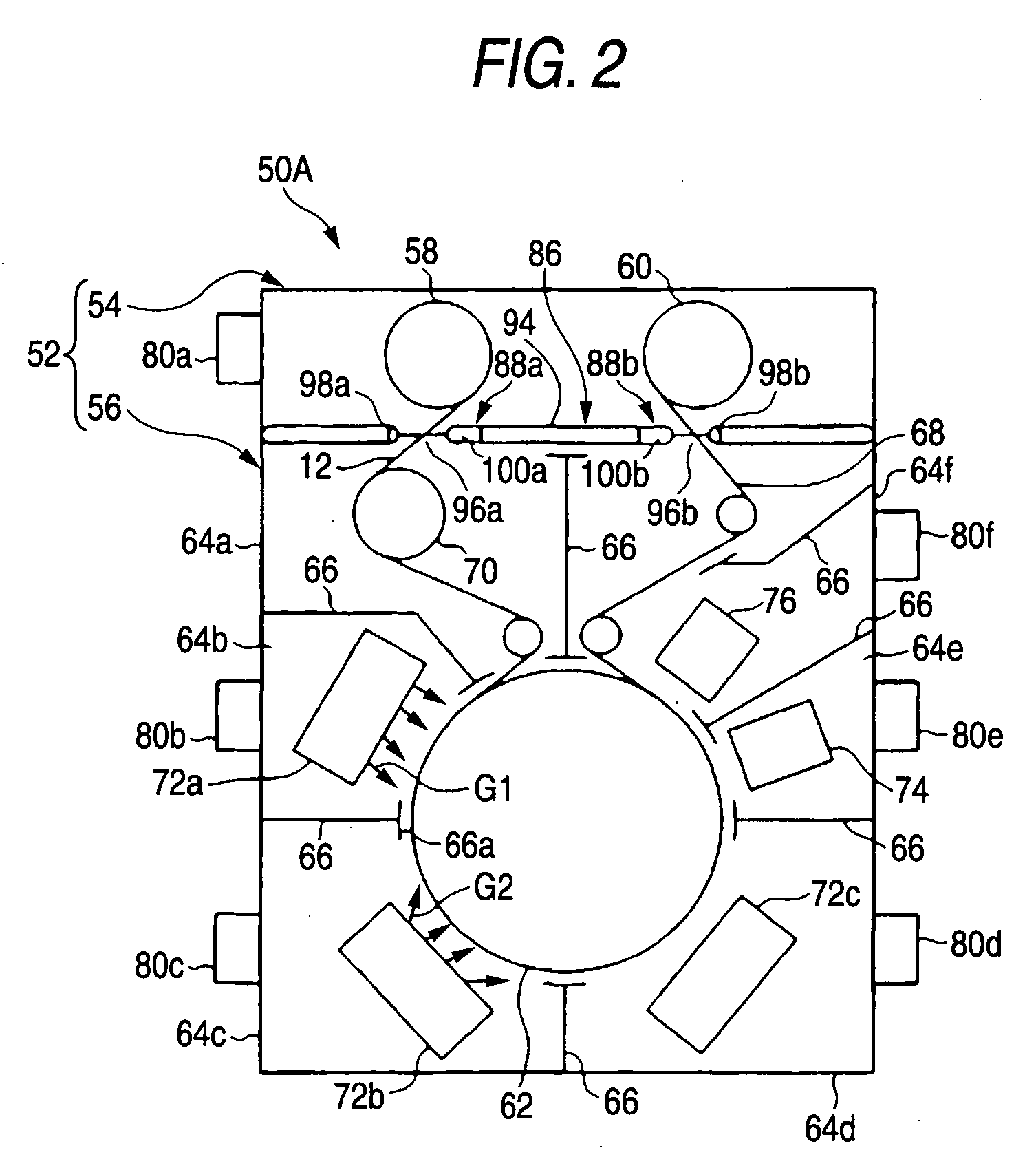
[0204] The resultant substrate 12 was attached to a feed roll 58 of an apparatus 50A shown in FIG. 2 according to the first embodiment, and was conveyed while bringing the substrate 12 into close contact with a water-cooled film forming roll 62...

example 2

[0210] Flexible disks 10 were produced in the same manner as Example 1 except for using an apparatus 50B shown in FIG. 7 according to the second embodiment. Materials and characteristics of the members contained in the first and second shutters 88a and 88b in the vacuum separator 86 were equal to those of Example 1.

example 3

[0211] Flexible disks 10 were produced in the same manner as Example 1 except that the first underlayer 16, second underlayer 18, magnetic layer 20, and protective layer 22 were formed on each of the both sides of the substrate 12 in 1 process (1 pass) by using an apparatus 50C shown in FIG. 8 according to the third embodiment. Materials and characteristics of the members contained in the first and second shutters 88a and 88b in the vacuum separator 86 were equal to those of Example 1.


PUM

PropertyMeasurementUnit
temperatureaaaaaaaaaa

Abstract

A process for producing a magnetic recording medium comprising: unrolling a flexible polymer substrate from a feed roll; forming a magnetic layer on at least one side of the flexible polymer substrate by a vacuum film forming method in a film forming chamber; and taking up the flexible polymer substrate on a take-up roll, wherein at least one of the feed roll and the take-up roll is replaced while maintaining a vacuum state for forming the magnetic layer in the film forming chamber.

Description

FIELD OF THE INVENTION [0001] The present invention relates to a process and an apparatus for producing a magnetic recording medium, the process comprising the steps of unrolling a flexible polymer substrate roll from a feed roll, forming a magnetic layer on at least one side of the flexible polymer substrate by a vacuum film forming method in a film forming chamber, and taking up the flexible polymer substrate on a take-up roll. BACKGROUND OF THE INVENTION [0002] Recent popularization of the internet has diversified the use of personal computers, including processing large volumes of moving image or sound data. With this trend, the demand for magnetic recording media, such as hard disks, with increased memory capacity has ever been increasing. [0003] In hard disk drives, when a magnetic disk is rotated, a magnetic head slightly flies from the magnetic disk surface to achieve noncontact magnetic recording. Thus, the magnetic head is prevented from coming into contact with the magnet...

Claims


Application Information

Patent Timeline
Patent Type & Authority Applications(United States)
IPC IPC(8): B05D5/12C23C16/00
CPCC23C14/562G11B5/851
Inventor MORIWAKI, KENICHIUSUKI, KAZUYUKINAKADA, JUNJI
Owner FUJIFILM CORP
Learn More