Wireless power receiving device

a power receiving device and wireless technology, applied in the direction of wireless communication, resonant antennas, near-field systems using receivers, etc., can solve the problems of disconnection, poor connection, and the like, and achieve the effect of reducing production costs, low cost, and reducing production costs

Active Publication Date: 2009-12-17
SEMICON ENERGY LAB CO LTD
View PDF33 Cites 108 Cited by
  • Summary
  • Abstract
  • Description
  • Claims
  • Application Information

AI Technical Summary

Benefits of technology

[0027]By using the structure of the wireless power receiving device of the invention, the power transmitter and receiver portion and the load portion may be easily removed. Accordingly, every time the frequency of the electromagnetic waves received at the first antenna circuit changes, the shape of the antenna may be adjusted by merely changing the power transmitter and receiver portion having the first antenna circuit. Therefore, the wireless power receiving device of the invention may be produced at low cost by reducing production cost for replacing the first antenna.
[0028]Moreover, in the present invention, the battery portion including the battery which accumulates electricity supplied through the electromagnetic waves and the antenna which receives the electromagnetic waves, and the load portion including the load supplied with electricity are formed separately so that the load portion is supplied with electricity through the radio (wireless) signal. Therefore, electricity may be transmitted from the battery portion which accumulates electricity supplied through the electromagnetic waves, to the load portion supplied with electricity without using a penetration electrode or a wire bonding or the like. Accordingly, defects such as disconnection or poor connection may be reduced.

Problems solved by technology

Moreover, in the case where the battery of the portable electronic device which accumulates electricity acquired upon reception of electromagnetic waves at the antenna is larger than a load to be supplied with electricity, it is hard to form the battery and the load supplied with electricity in the same manufacturing step.
However, in the case where the load supplied with electricity and the battery connected to the antenna are formed in the different steps and are connected with a penetration electrode, a wire bonding, or the like to perform power transmission between them, defects such as disconnection, poor connection, and the like may occur.

Method used


Image

  • Wireless power receiving device
  • Wireless power receiving device
  • Wireless power receiving device

Examples


embodiment mode 1

[0049]This embodiment mode will describe an example of a wireless power receiving device of the present invention with reference to drawings.

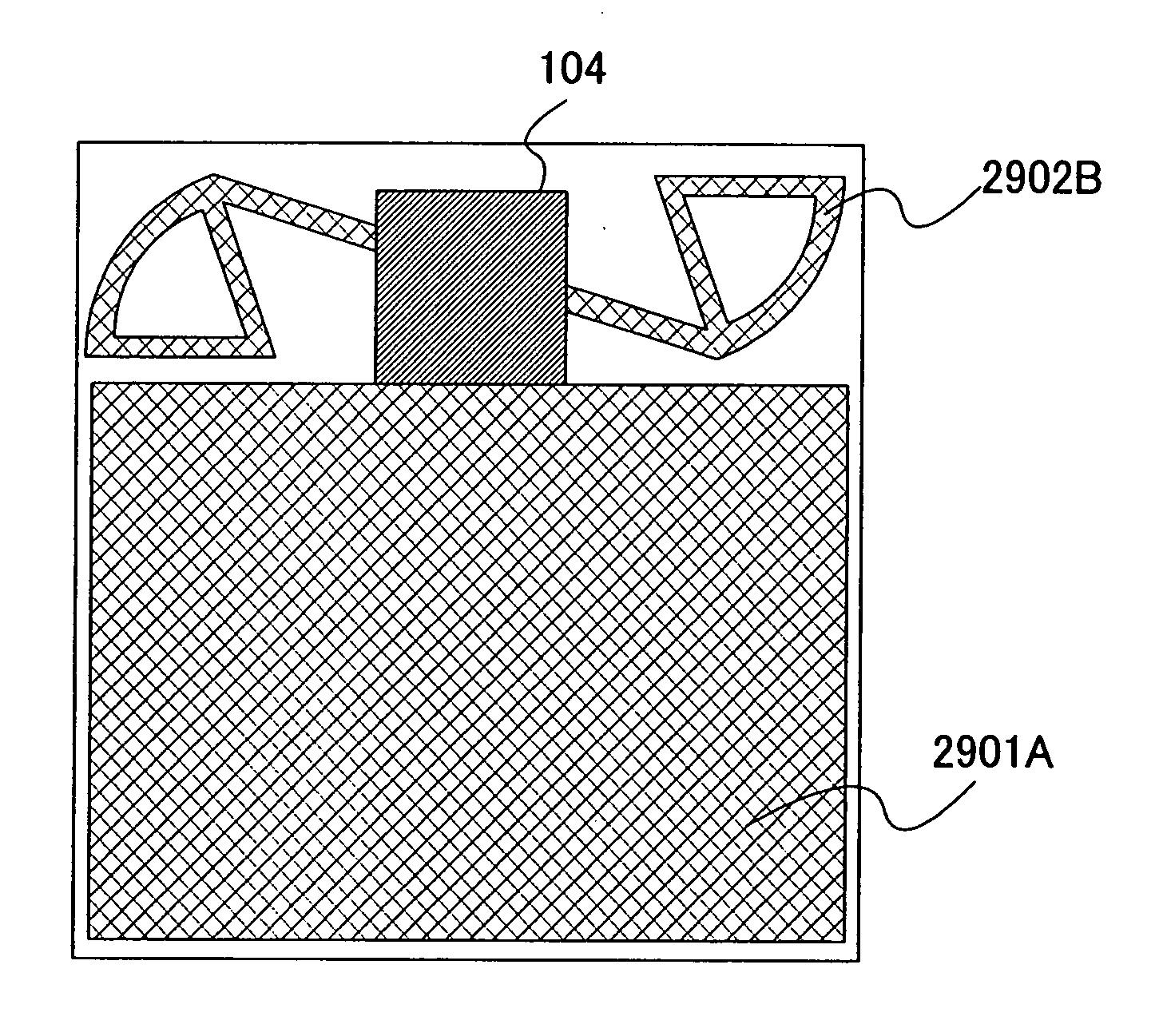
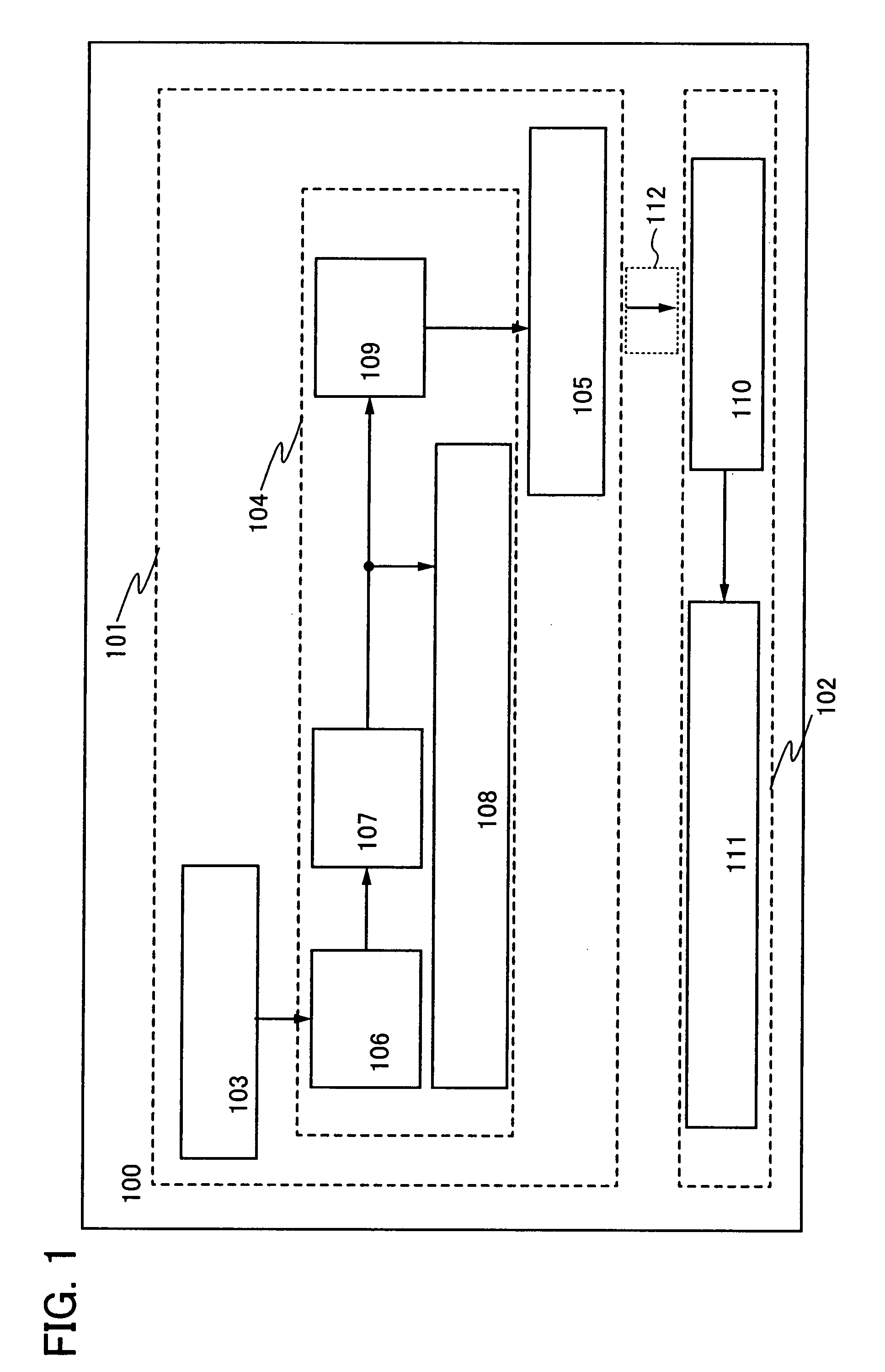
[0050]A wireless power receiving device 100 shown in this embodiment mode includes a power transmitter and receiver portion 101 and a load portion 102. The power transmitter and receiver portion 101 includes a first antenna circuit 103, a battery portion 104, and a second antenna circuit 105. The battery portion 104 includes a rectifier circuit 106, a charging control circuit 107, a battery 108, and a discharging control circuit 109. In addition, the load portion 102 includes a third antenna circuit 110 and a load 111.

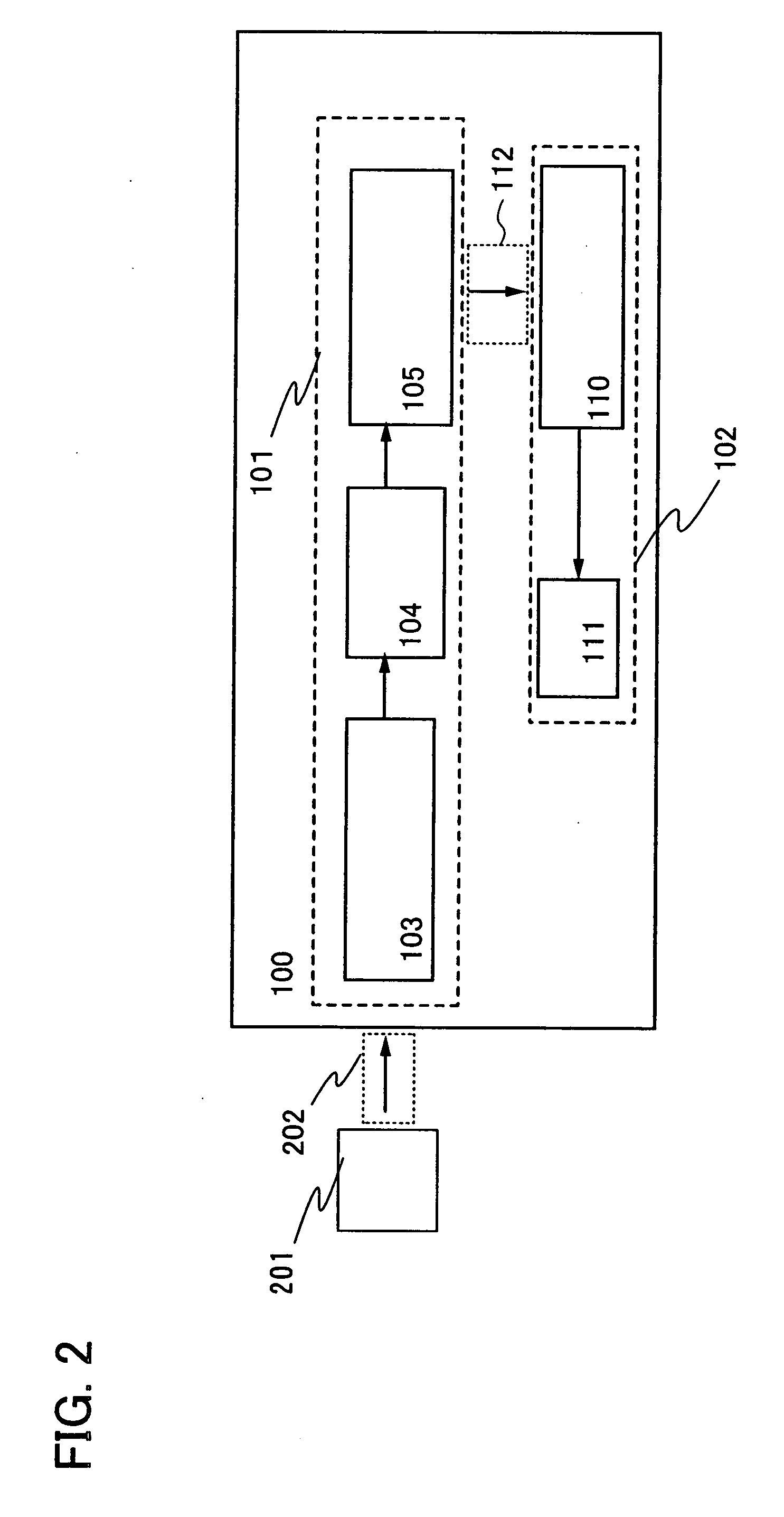
[0051]Note that in the wireless power receiving device 100 shown in FIG. 1, electromagnetic waves 202 are transmitted to the first antenna circuit 103 in the power transmitter and receiver portion 101, by an electromagnetic wave feeder 201 provided outside of the wireless power receiving device 100 as shown in FIG. 2. The electrom...

embodiment mode 2

[0088]This embodiment mode will describe an example of the wireless power receiving device provided with an RF tag as the load of the wireless power receiving device shown in Embodiment Mode 1 with reference to drawings. Note that the structure in this embodiment mode is not limited to the RF tag and may be applied to any data transmitter and receiver device which is capable of communicating data wirelessly.

[0089]An example of the wireless power receiving device in this embodiment mode will be described with reference to FIG. 13.

[0090]The wireless power receiving device 1300 shown in FIG. 13 includes the power transmitter and receiver portion 101, and the load portion 102. The power transmitter and receiver portion 101 includes the first antenna circuit 103, the battery portion 104, and the second antenna circuit 105. In addition, the load portion 102 includes the third antenna circuit 110 and an RF tag 1301.

[0091]Note that the structures of the first antenna circuit 103, the batter...

embodiment mode 3

[0101]In this embodiment mode, as the load in the wireless power receiving device shown in Embodiment Mode 2, one example of the wireless power receiving device including the rectifier circuit, the power supply circuit, and the signal processing circuit in the RF tag of Embodiment Mode 2 will be described with reference to drawings. In this embodiment mode, a configuration in which communication signals are transmitted to and received from the outside and electricity is supplied through the radio signals, by using a power transmitter and receiver portion will be described.

[0102]One example of the wireless power receiving device in this embodiment mode will be described with reference to FIG. 16.

[0103]A wireless power receiving device 1600 shown in FIG. 16 includes the power transmitter and receiver portion 101, the load portion 102, and a signal transmitter / receiver portion 1601. The power transmitter and receiver portion 101 includes the first antenna circuit 103, the battery porti...


PUM


Abstract

To provide a wireless power receiving device and an electronic device having the wireless power receiving device whose production costs do not increase even when frequency of electromagnetic waves received for power supply varies. Further, to provide a wireless power receiving device capable of power transmission without disconnection or poor connection when a load supplied with electricity and a battery connected to an antenna are manufactured in different steps. A power transmitter and receiver portion having first and second antenna circuits and a battery portion and a load portion having a third antenna circuit are provided to charge a battery of the battery portion with a first radio signal received at the first antenna circuit and transmit electricity stored in the battery portion as a second radio signal from the second antenna circuit to the third antenna circuit so that the third antenna circuit supplies electricity to the load.

Description

BACKGROUND OF THE INVENTION[0001]1. Field of the Invention[0002]The present invention relates to a wireless power receiving device into which electricity is supplied wirelessly.[0003]2. Description of the Related Art[0004]Since a variety of electronic devices became widespread, many kinds of products have been shipped to market. In recent years, particularly, portable electronic devices for outdoor use have been remarkably widespread.[0005]As an example of a portable electronic device for outdoor use, an RFID (radio frequency identification) tag (hereinafter referred to as an RF tag) has been actively researched and developed for practical use. The RF tag may be classified into two types: an active RF tag and a passive RF tag. On the other hand, other than the active RF tag and the passive RF tag, another type of an RF tag including a battery which is charged by using electromagnetic waves of a cell phone or the like in order to acquire electricity to drive the RF tag, has been deve...

Claims


Application Information

Patent Timeline
Patent Type & Authority Applications(United States)
IPC IPC(8): G06K19/06G06K19/07H04B5/02
CPCG06K19/0701G06K19/0702G06K19/0715G06K19/0723G06K19/0724G06K19/07749H04B5/0037H01Q1/2225H01Q9/16H01Q9/27H02J7/0044H02J7/025G06K19/07767H02J50/10H02J50/20H02J50/27H02J50/12
Inventor OSADA, TAKESHI
Owner SEMICON ENERGY LAB CO LTD
Why Eureka
Try Eureka