
Method of producing a perpendicular magnetic recording medium

Inactive Publication Date: 2012-07-12
WD MEDIA SINGAPORE PTE
View PDF9 Cites 69 Cited by
  • Summary
  • Abstract
  • Description
  • Claims
  • Application Information

AI Technical Summary

Benefits of technology

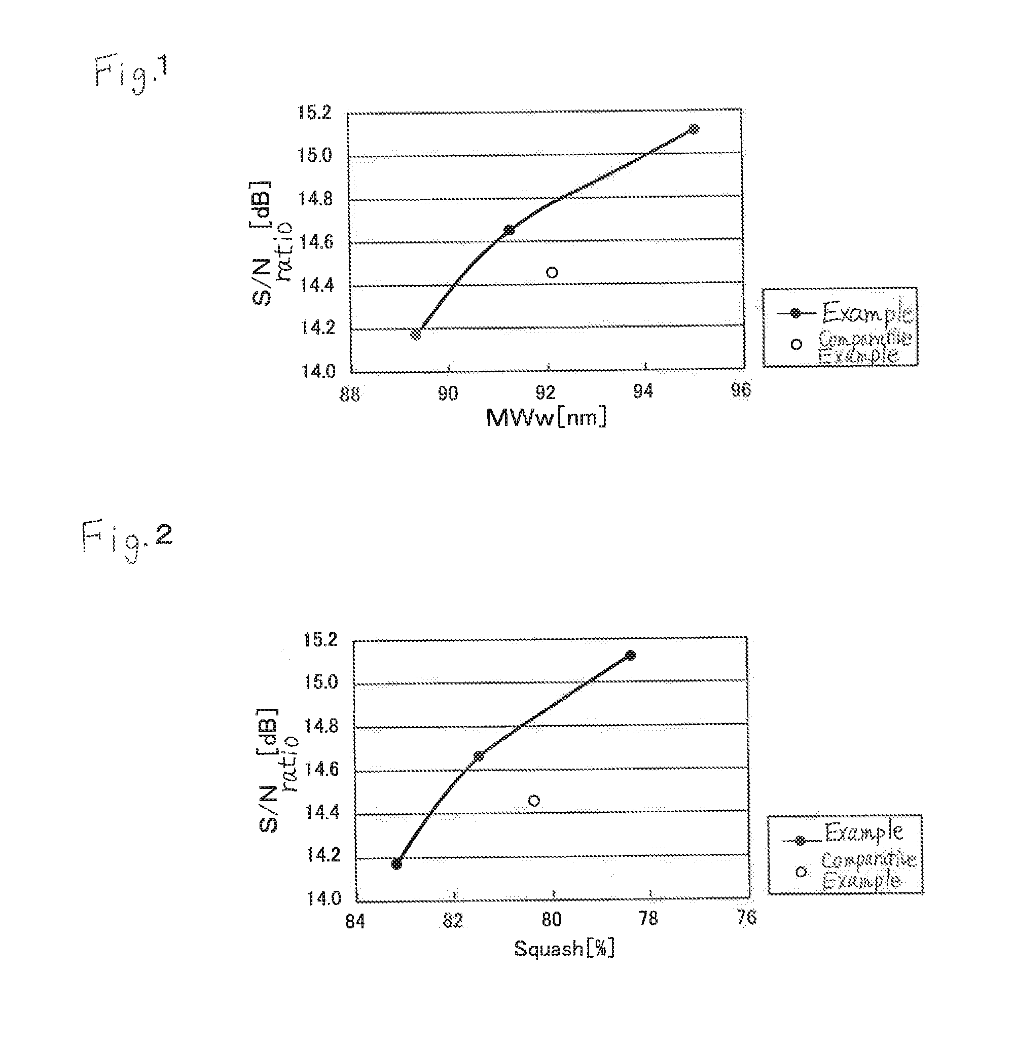
[0013]Under the conventional circumstances, an object of the present invention is to provide a method for manufacturing a perpendicular magnetic recording medium, which can improve the electromagnetic conversion characteristics to achieve the higher recording density.
[0015]Thus, the present inventors have intensively studied and as a result found that by increasing the number of necessary chambers according to the conditions, the underlayer having a desired thickness can be obtained and the electromagnetic conversion characteristics can be improved without decreasing a tact time even during the deposition at the low rate. As a result, the present invention has been completed. That is, the present invention has the following constructions so as to achieve the above object.
[0026]According to the invention, the underlayer is formed by sputtering deposition, and includes a low-gas-pressure deposited layer deposited at a low gas pressure during the deposition and a high-gas-pressure deposited layer deposited at a high gas pressure during the deposition. The high-gas-pressure deposited layer is formed of a multilayer deposited by decreasing a deposition rate in a stepwise manner. This arrangement improves the perpendicular orientation and the crystal isolation property due to the miniaturization of the underlayer directly below the magnetic recording layer, and thus can improve the electromagnetic conversion characteristics of the magnetic recording layer. Accordingly, the perpendicular magnetic recording medium can be provided which achieves the much higher recording density.

Problems solved by technology

Thus, this deposition is not appropriate for commercial production.

Method used


Image

  • Method of producing a perpendicular magnetic recording medium

Examples


example 1

[0055]An amorphous aluminosilicate glass was molded into a disk shape by direct press to produce a glass disk. The glass disk was cut, polished, and chemically hardened in sequence, whereby a flat non-magnetic glass substrate formed of the chemically hardened glass disk was obtained. The diameter of the disk was 65 mm. The surface roughness of the main surface of the glass substrate was measured by an atomic force microscope (AFM) to obtain the following result: Rmax was 2.18 nm, and Ra was 0.18 nm. The thus-obtained substrate was found to have a flat surface. The Rmax and Ra were measured in accordance to Japanese Industrial Standards (JIS).

[0056]Then, an adhesive layer, a soft magnetic layer, a seed layer, an underlayer, a perpendicular magnetic recording layer, an exchange-coupling control layer, an auxiliary recording layer, and a protective layer were deposited on the glass substrate in that order by DC magnetron sputtering using a cluster type stationary facing sputtering devi...


PUM

PropertyMeasurementUnit
Pressureaaaaaaaaaa
Deposition rateaaaaaaaaaa
Pressureaaaaaaaaaa

Abstract

To provide a method for manufacturing a perpendicular magnetic recording medium which has improved electromagnetic conversion characteristics, and thus making it possible to achieve the much higher recording density.Disclosed is a method for manufacturing a perpendicular magnetic recording medium to be used for recording information by a perpendicular magnetic recording system, the perpendicular magnetic recording medium including at least a soft magnetic layer, an underlayer, and a magnetic recording layer on a substrate. In the method, the underlayer is formed by sputtering deposition, including a low-gas-pressure deposited layer deposited at a low gas pressure during the deposition, and a high-gas-pressure deposited layer deposited at a high gas pressure during the deposition. The high-gas-pressure deposited layer is formed of a multilayer deposited by decreasing a deposition rate in a stepwise manner.

Description

BACKGROUND OF THE INVENTION[0001]1. Technical Field[0002]The present invention relates to a method for manufacturing a perpendicular magnetic recording medium to be mounted on a magnetic disk device of a perpendicular magnetic recording system, such as a hard disk drive (HDD).[0003]2. Background Art[0004]With increasing capacity for information processing, various types of information recording techniques have been recently developed. In particular, the HDD using a magnetic recording technique has been continuing to increase a surface recording density at a rate of about 100% per year. In recent years, magnetic disks of 2.5 inches in diameter for use in the HDD or the like have been required to have an information recording capacity exceeding 250 Gbyte per piece. An information recording density exceeding 400 Gbit per square inch is required so as to achieve such a requirement. In order to achieve the high recording density in the magnetic disk to be used in the HDD or the like, it ...

Claims


Application Information

Patent Timeline
IPC IPC(8): C23C14/34
CPCG11B5/82G11B5/851G11B5/8404
Inventor FUKUURA, MOTOIKOIKE, TAKASHIFURUGOORI, SHIGEAKIUEMURA, MASAKI
Owner WD MEDIA SINGAPORE PTE
Learn More