Perpendicular magnetic recording disk and manufacturing method thereof

a technology of magnetic recording disk and manufacturing method, which is applied in the direction of record information storage, instruments, ultrathin/granular films, etc., can solve the problems of affecting the increase in the recording density of the magnetic disk, and achieve the effects of improving the s/n ratio, increasing the recording density, and increasing the noise of the d

Active Publication Date: 2013-12-10
WESTERN DIGITAL TECH INC
View PDF23 Cites 69 Cited by
  • Summary
  • Abstract
  • Description
  • Claims
  • Application Information

AI Technical Summary

Benefits of technology

[0034]According to this invention, it is possible to provide a perpendicular magnetic recording disk that can contribute to increasing the recording density by improving the S / N ratio in high density recording without causing an increase in DC noise, degradation in thermal stability, and degradation in recording capability, and a method of manufacturing such a disk.

Problems solved by technology

However, in the case of the conventionally commercialized magnetic disk of the in-plane magnetic recording type (also called the longitudinal magnetic recording type or the horizontal magnetic recording type), as a result of the size reduction of the magnetic crystal grains, there has arisen a thermal fluctuation phenomenon where thermal stability of recording signals is degraded due to superparamagnetism to thereby cause loss of the recording signals, which has thus become an impeding factor for the increase in recording density of the magnetic disk.

Method used


Image

  • Perpendicular magnetic recording disk and manufacturing method thereof
  • Perpendicular magnetic recording disk and manufacturing method thereof
  • Perpendicular magnetic recording disk and manufacturing method thereof

Examples


example 1

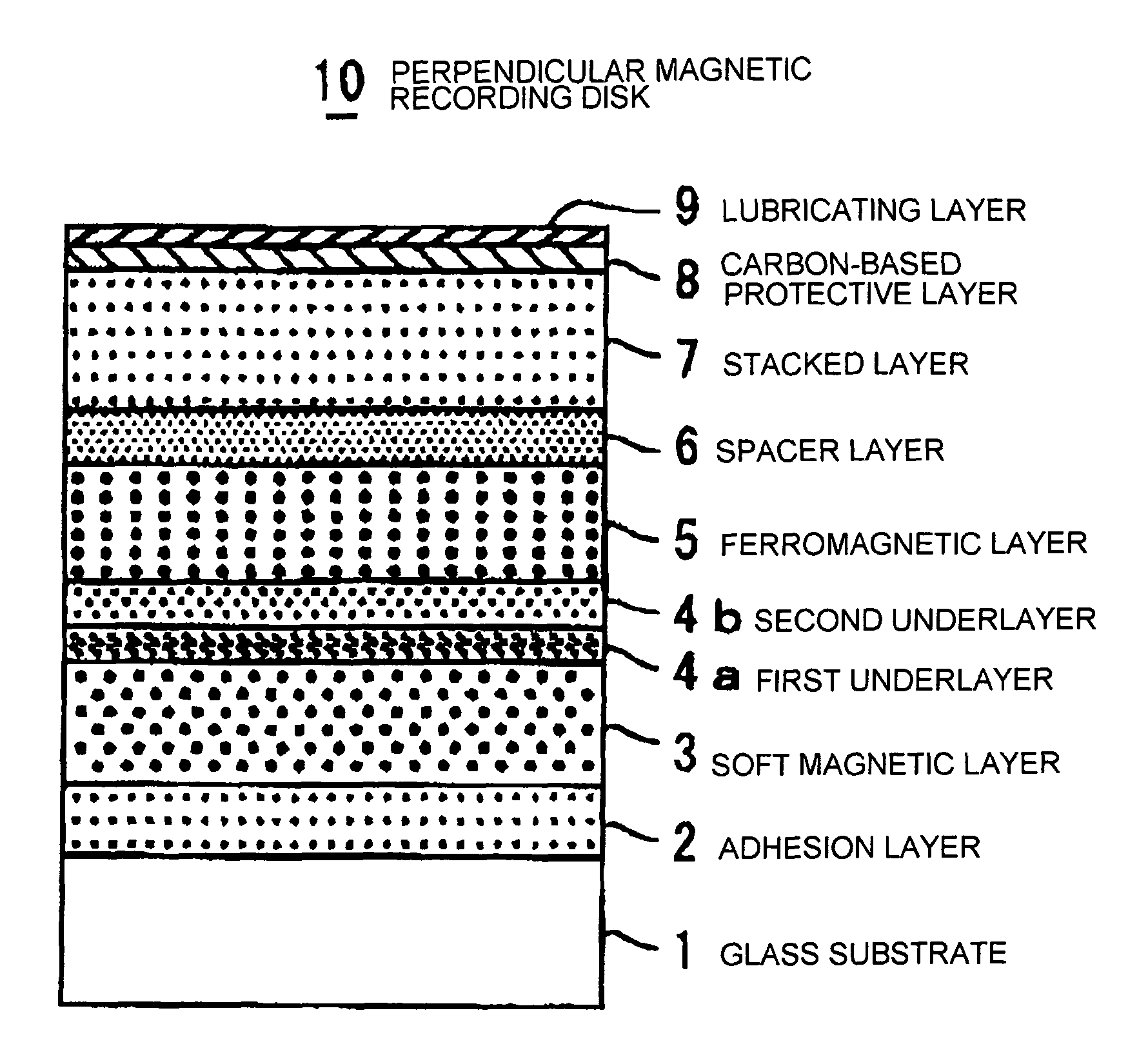
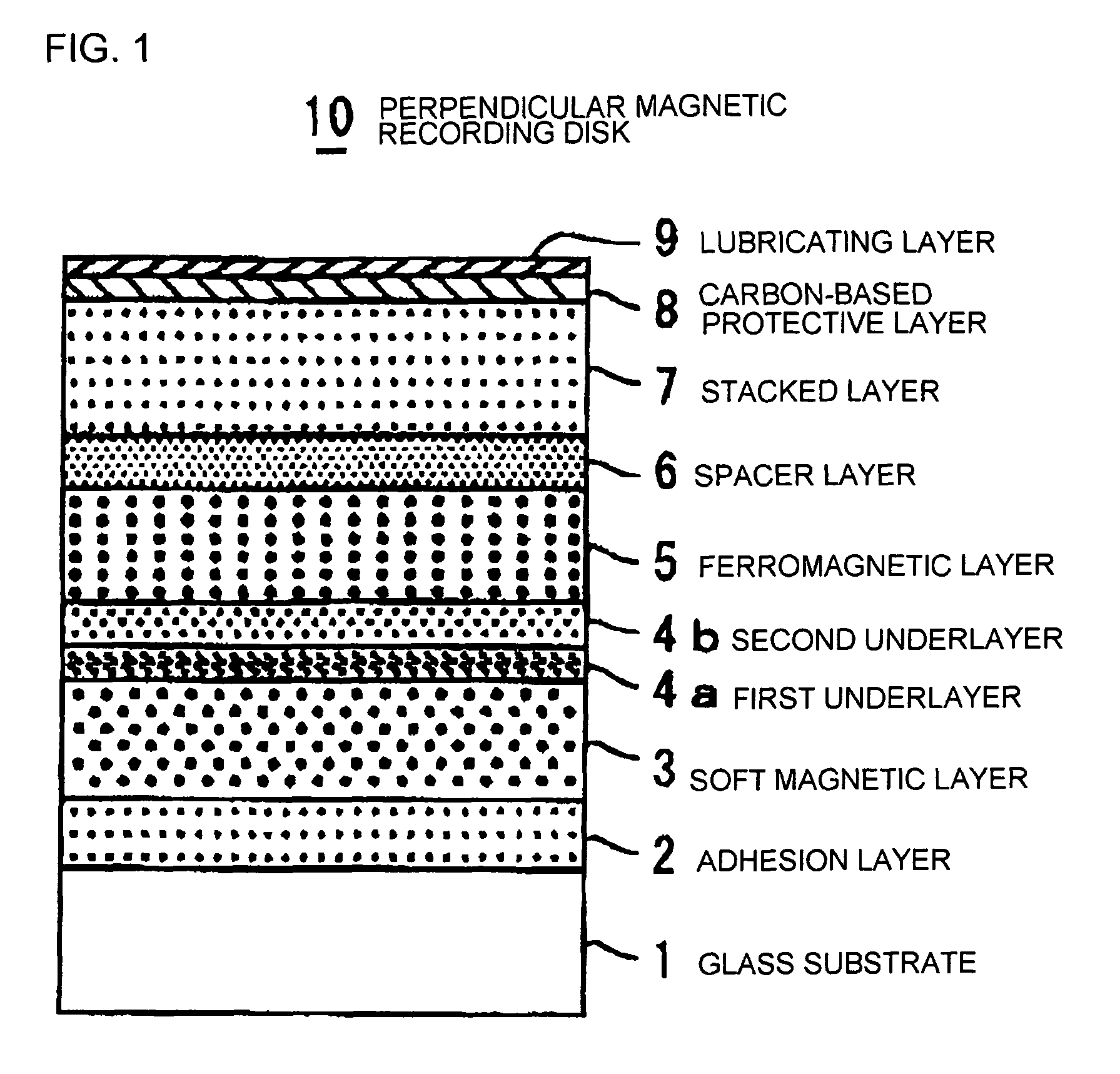
[0036]An amorphous aluminosilicate glass was molded into a disk shape by direct press, thereby producing a glass disk. This glass disk was ground, polished, and chemically strengthened in order, thereby obtaining a smooth nonmagnetic glass substrate 1 in the form of a chemically strengthened glass disk. The disk diameter was 65 mm. The surface roughness of the main surface of the glass substrate 1 was measured by an AFM (atomic force microscope) and it was a smooth surface shape with Rmax being 4.8 nm and Ra being 0.42 nm. Rmax and Ra follow Japanese Industrial Standard (JIS). Then, by the use of an evacuated film forming apparatus, an adhesion layer 2 and a soft magnetic layer 3 were formed in order on the obtained glass substrate 1 in an Ar atmosphere according to the DC magnetron sputtering method. In this event, the adhesion layer 2 was formed by the use of a Ti target so as to be a Ti layer having a thickness of 20 nm. On the other hand, the soft magnetic layer 3 was formed by ...

example 2

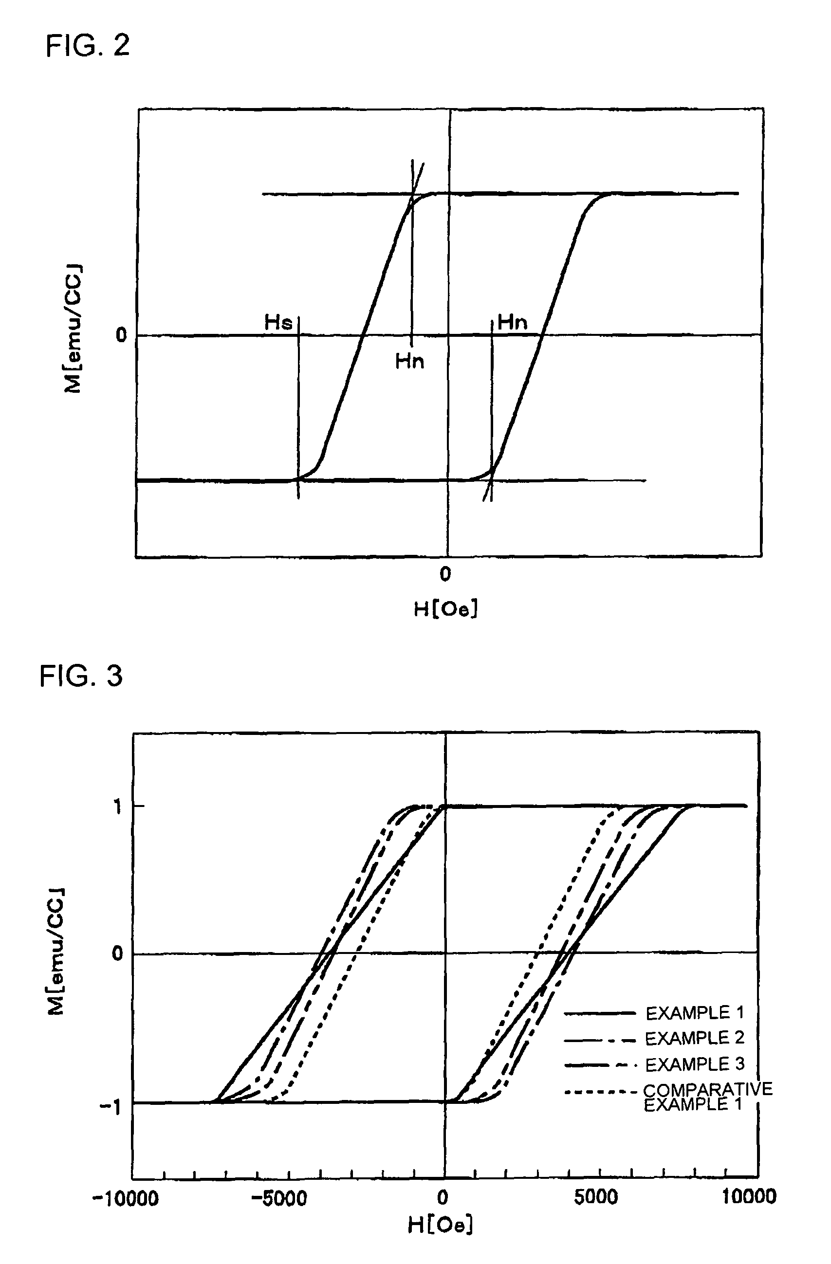
[0042]A perpendicular magnetic recording disk was obtained in the same manner as in Example 1 except that the stacked layer 7 in Example 1 was changed to alternate-layered films of two cycles of CoB and Pd (Example 2). The total thickness of the stacked layer 7 in the perpendicular magnetic recording disk of this example was 2.4 nm. The orientation of a perpendicular magnetic recording layer in the obtained perpendicular magnetic recording disk was analyzed by the X-ray diffraction method and, like in Example 1, the c-axis of a hcp (hexagonal close-packed) crystal structure was oriented in a direction perpendicular to the disk surface. Further, a ferromagnetic layer 5 in the obtained perpendicular magnetic recording disk was analyzed in detail by the use of the transmission electron microscope (TEM) and it had a granular structure like in Example 1. Specifically, it was confirmed that grain boundary portions made of Si oxide were formed between crystal grains of the hcp crystal stru...

example 3

[0043]A perpendicular magnetic recording disk was obtained in the same manner as in Example 1 except that the stacked layer 7 in Example 1 was changed to alternate-layered films of five cycles of CoB and Pd (Example 3). The total thickness of the stacked layer 7 in the perpendicular magnetic recording disk of this example was 6.0 nm. The orientation of a perpendicular magnetic recording layer in the obtained perpendicular magnetic recording disk was analyzed by the X-ray diffraction method and, like in Example 1, the c-axis of a hcp (hexagonal close-packed) crystal structure was oriented in a direction perpendicular to the disk surface. Further, a ferromagnetic layer 5 in the obtained perpendicular magnetic recording disk was analyzed in detail by the use of the transmission electron microscope (TEM) and it had a granular structure like in Example 1. Specifically, it was confirmed that grain boundary portions made of Si oxide were formed between crystal grains of the hcp crystal str...


PUM

PropertyMeasurementUnit
thicknessaaaaaaaaaa
thicknessaaaaaaaaaa
thicknessaaaaaaaaaa

Abstract

A magnetic disk 10 for use in perpendicular magnetic recording has at least a magnetic recording layer on a substrate 1. The magnetic recording layer is composed of a ferromagnetic layer 5 of a granular structure containing silicon (Si) or an oxide of silicon (Si) between crystal grains containing cobalt (Co), a stacked layer 7 having a first layer containing cobalt (Co) or a Co alloy and a second layer containing palladium (Pd) or platinum (Pt), and a spacer layer 6 interposed between the ferromagnetic layer 5 and the stacked layer 7. After forming the ferromagnetic layer 5 on the substrate 1 by sputtering in an argon gas atmosphere, the stacked layer 7 is formed by sputtering in the argon gas atmosphere at a gas pressure lower than that used when forming the ferromagnetic layer 5.

Description

TECHNICAL FIELD[0001]This invention relates to a perpendicular magnetic recording disk adapted to be mounted in a perpendicular magnetic recording type HDD (hard disk drive) or the like.BACKGROUND ART[0002]Various information recording techniques have been developed following the increase in volume of information processing in recent years. Particularly, the areal density of a HDD (hard disk drive) using the magnetic recording technique has been increasing at an annual rate of about 100%. Recently, the information recording capacity exceeding 60 GB has been required per 2.5-inch magnetic disk adapted for use in a HDD or the like. In order to satisfy such a requirement, it is necessary to realize an information recording density exceeding 100 Gbits / inch2. In order to achieve the high recording density in the magnetic disk for use in the HDD or the like, it is necessary to reduce the size of magnetic crystal grains forming a magnetic recording layer serving to record information signa...

Claims


Application Information

Patent Timeline
Patent Type & Authority Patents(United States)
IPC IPC(8): G11B5/673
CPCB82Y25/00G11B5/66G11B5/851H01F10/007G11B2005/0029H01F10/16H01F41/18
Inventor SONOBE, YOSHIAKIUMEZAWA, TEIICHIROTAKASU, CHIKARA
Owner WESTERN DIGITAL TECH INC
Why Eureka
Try Eureka