Optical recording medium and method for manufacturing same

a technology of optical recording medium and manufacturing method, which is applied in the direction of data recording, record carrier material, instruments, etc., can solve the problems of inability to obtain excellent signal characteristics, inability to obtain high reliability, and inability to allow the disc surface relative to the optical axis of the optical pickup to tilt smaller, so as to achieve excellent signal characteristics and high reliability.

Active Publication Date: 2005-06-16
SONY CORP
View PDF10 Cites 4 Cited by
  • Summary
  • Abstract
  • Description
  • Claims
  • Application Information

AI Technical Summary

Benefits of technology

[0028] Accordingly, an object of the present invention is to provide, in an optical recording medium in which by focusing light having a wavelength in a range of 400 nm or more and 410 nm or less with an optical system having a numeral aperture in the range of 0.84 or more and 0.86 or less followed by irradiating through a light transmissive layer on an information signal portion, and thereby a information signal is recorded and reproduced, a optical recording medium that can obtain excellent signal characteristics and high reliability; and a manufacturing method thereof.

Problems solved by technology

However, when an object lens is made higher in the NA, optical aberration caused by tilt of a disc becomes larger, and thereby a problem in that an allowance of the tilt of the disc surface relative to an optical axis of an optical pickup becomes smaller is caused.
However, when the present inventors have repeated manufacturing the abovementioned next generation optical recording media, conducted various experiments of the next generation optical recording media and studied variously based on the experimental results, the inventors have come to find a problem in that in the abovementioned next generation optical recording media, excellent signal characteristics and high reliability cannot be obtained.
However, in the abovementioned existing next generation optical recording media, there is a problem in that when an information signal is recorded at a high speed as mentioned above, excellent signal characteristics and high reliability cannot be obtained.

Method used


Image

  • Optical recording medium and method for manufacturing same
  • Optical recording medium and method for manufacturing same
  • Optical recording medium and method for manufacturing same

Examples


examples 1 through 4

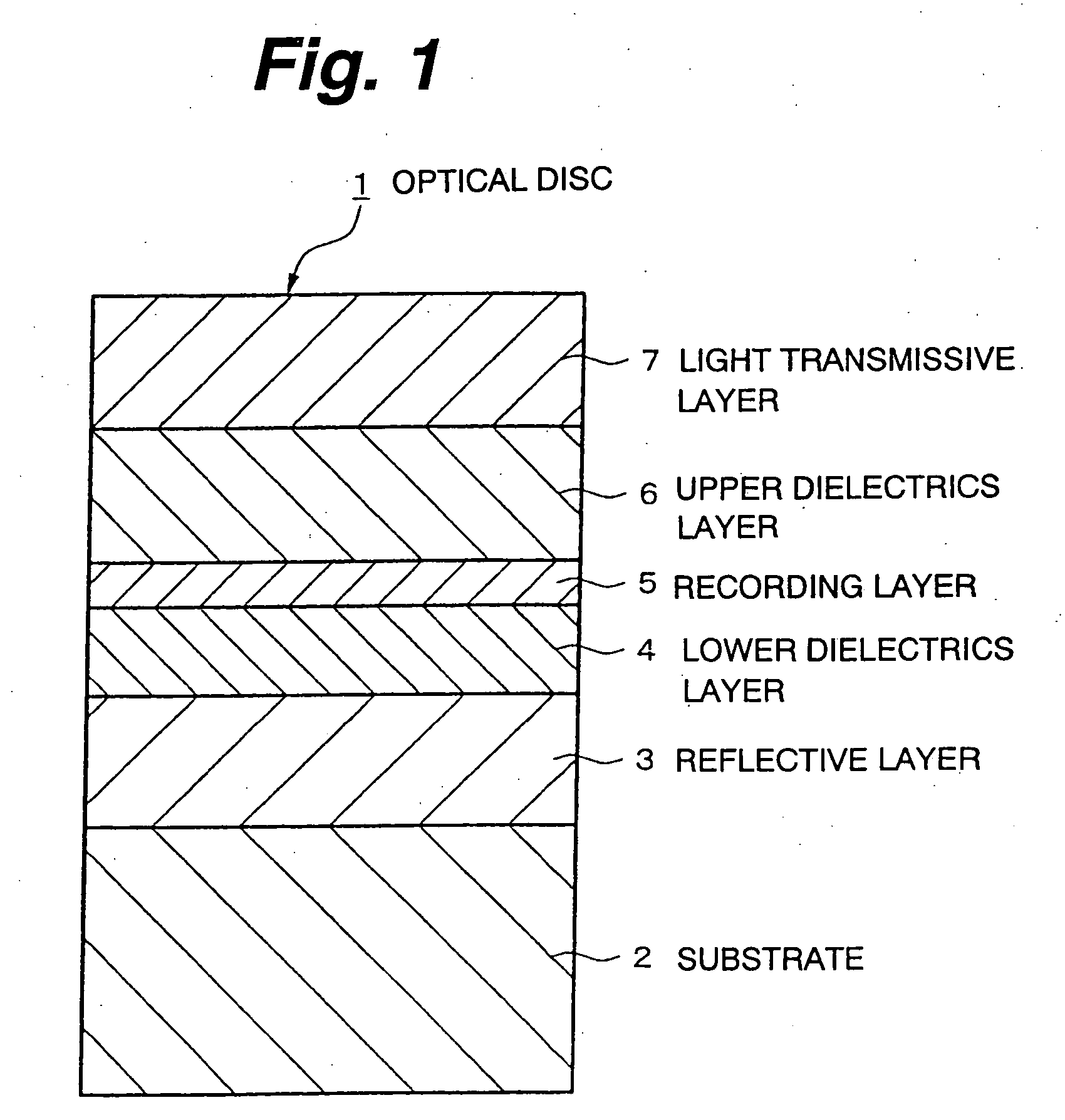
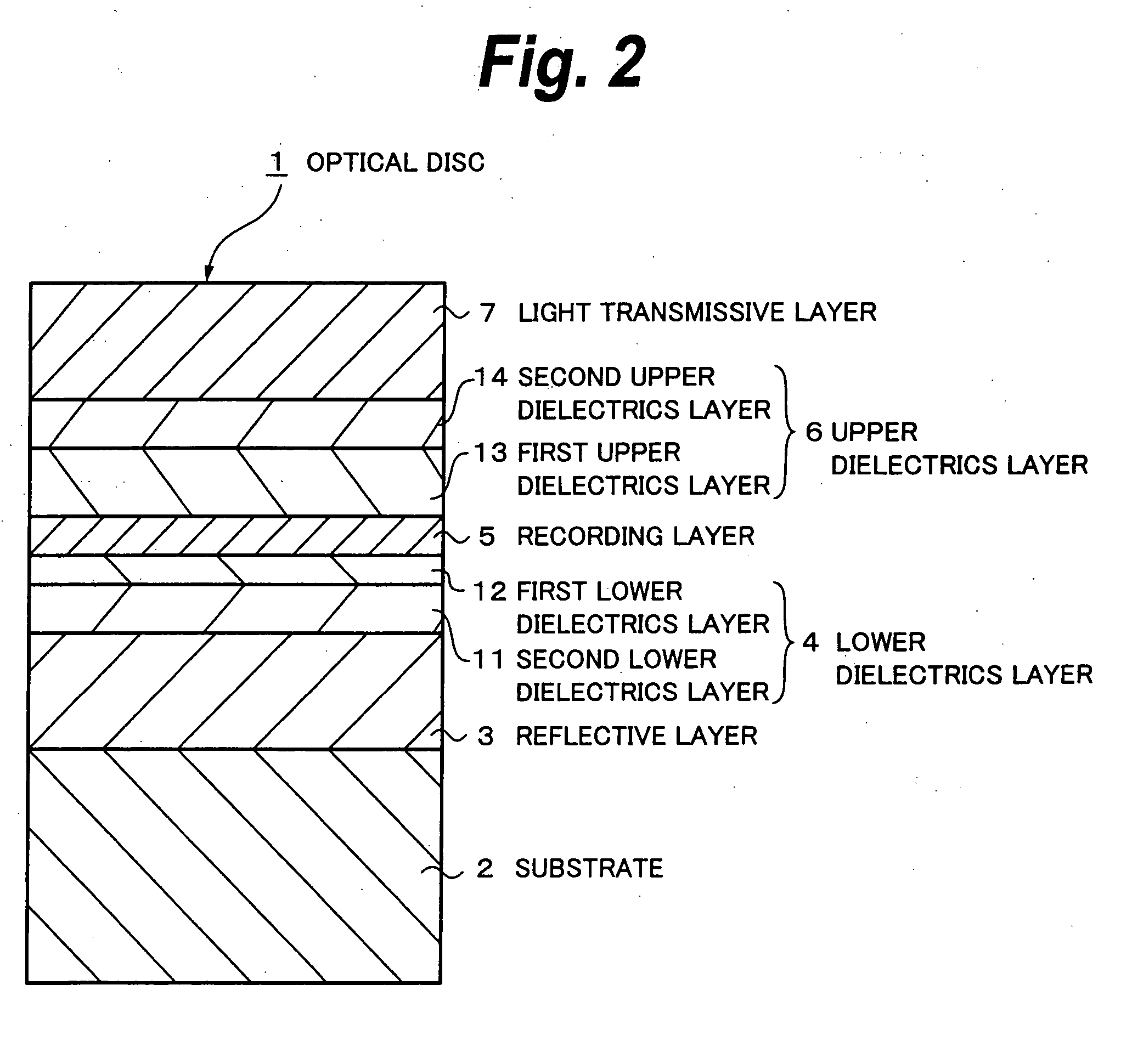
[0129] Examples 1 through 4 relates to optical discs formed by laminating, on a substrate 2, a reflective layer 3 made of AgNdCu, a second lower dielectrics layer 11 made of Si3N4, a first lower dielectrics layer 12 made of a ZnS—SiO2 mixture, a recording layer 5 made of GeSbTe, a first upper dielectrics layer 13 made of a ZnS—SiO2 mixture, a second upper dielectrics layer 14 made of Si3N4, and a light transmissive layer 7. The substrate 2 has a diameter of 120 mm and a thickness of 1.1 mm. On one main surface on a side on which the reflective layer 3 is formed, irregularities called grooves or lands are formed and a width of repetition of the irregularities (track pitch) is 0.32 μm. A content of Nd in the reflective layer 3 is 0.4 atomic percent and that of Cu is 0.6 atomic percent. Furthermore, the light transmissive layer 7 is formed by laminating a light transmissive sheet having a planar annular shape through an adhesive layer made of a pressure sensitive adhesive (PSA) coated ...

examples 5 through 8

[0143] Examples 5 through 8 relate to optical discs that are different from each other in thickness of the second lower dielectrics layer 11, and the thicknesses thereof are, in turn of examples 5 through 8, 4 nm, 8 nm, 14 nm and 18 nm. On the other hand, thicknesses of the respective layers other than the second lower dielectrics layer 11 are the same, and the reflective layer 3, the first lower dielectrics layer 12, the recording layer 5, the first upper dielectrics layer 13 and the second upper dielectrics layer 14, respectively, are 100 nm, 6 nm, 10 nm, 8 nm and 40 nm in the thickness. A thickness of the second lower dielectrics layer 11 was determined by properly adjusting a time based on a calibration curve obtained from relationship between a deposition time and a film thickness. Other than these are similar to examples 1 through 4.

examples 9 through 11

[0144] Examples 9 through 11 relate to optical discs that are different in thickness of the first lower dielectrics layer 12 from each other, and the thicknesses thereof are, in turn of examples 9 through 11, respectively, 4 nm, 10 nm and 12 nm. On the other hand, thicknesses of the respective layers other than the first lower dielectrics layer 12 are the same, and the reflective layer 3, the second lower dielectrics layer 11, the recording layer 5, the first upper dielectrics layer 13 and the second upper dielectrics layer 14, respectively, are 100 nm, 8 nm, 10 nm, 8 nm and 40 nm in the thickness. A thickness of the first lower dielectrics layer 12 was determined by properly adjusting a time based on a calibration curve obtained from relationship between a deposition time and a film thickness. Other than these are similar to examples 1 through 4.


PUM

PropertyMeasurementUnit
wavelengthaaaaaaaaaa
thicknessaaaaaaaaaa

Abstract

In an optical recording medium 1 having a configuration in which on one main surface of a substrate 2, a reflective layer 3, a lower dielectrics layer 4, a recording layer 5, an upper dielectrics layer 6 and a light transmissive layer 7 are sequentially laminated, the lower dielectrics layer 4 is formed of a first lower dielectrics layer and a second lower dielectrics layer that inhibits a material that constitutes the first lower dielectrics layer and a material that constitutes the reflective layer 3 from reacting, and the upper dielectrics layer 6 is formed of a first upper dielectrics layer and a second upper dielectrics layer that inhibits a material that constitutes the first upper dielectrics layer and a material that constitutes the light transmissive layer 7 from reacting.

Description

TECHNICAL FIELD [0001] The present invention relates to an optical recording medium and a manufacturing method thereof, in particular, one that can be preferably applicable to an optical recording medium in which laser light is irradiated from a side on which a protective layer is disposed to protect an information signal portion, and thereby the information signal is recorded and reproduced. BACKGROUND ART [0002] In the field of information recording, studies and developments of optical information recording systems have been variously forwarded. The optical information recording system has many advantages in that (1) non-contact recording and / or reproducing can be realized, (2) the recording density more than one digit higher than that of a magnetic recording system can be attained, (3) less expensive and large capacity file can be realized and so on. Accordingly, a wide application from industrial uses to consumer uses is in consideration. [0003] Optical recording media that use ...

Claims


Application Information

Patent Timeline
Patent Type & Authority Applications(United States)
IPC IPC(8): B32B3/02G11B7/24G11B7/24035G11B7/24056G11B7/24062G11B7/241G11B7/243G11B7/2433G11B7/2437G11B7/254G11B7/256G11B7/257G11B7/2578G11B7/258G11B7/259G11B7/26
CPCG11B7/241G11B2007/25716G11B7/2533G11B7/2534G11B7/256G11B7/2578G11B7/259G11B2007/24312G11B2007/24314G11B2007/24316G11B2007/25706G11B2007/2571G11B2007/25713G11B2007/25715G11B7/2531G11B7/2433G11B7/26
Inventor ABIKO, TORUIKEDA, ETSUROFURUICHI, NOBUAKITAKASE, FUMINORI
Owner SONY CORP
Why Eureka
Try Eureka