Photoelectric coupling assembly and method of coupling optical fibers and light receiving/emitting elements
- Summary
- Abstract
- Description
- Claims
- Application Information
AI Technical Summary
Benefits of technology
Problems solved by technology
Method used
Image


Examples
Embodiment Construction
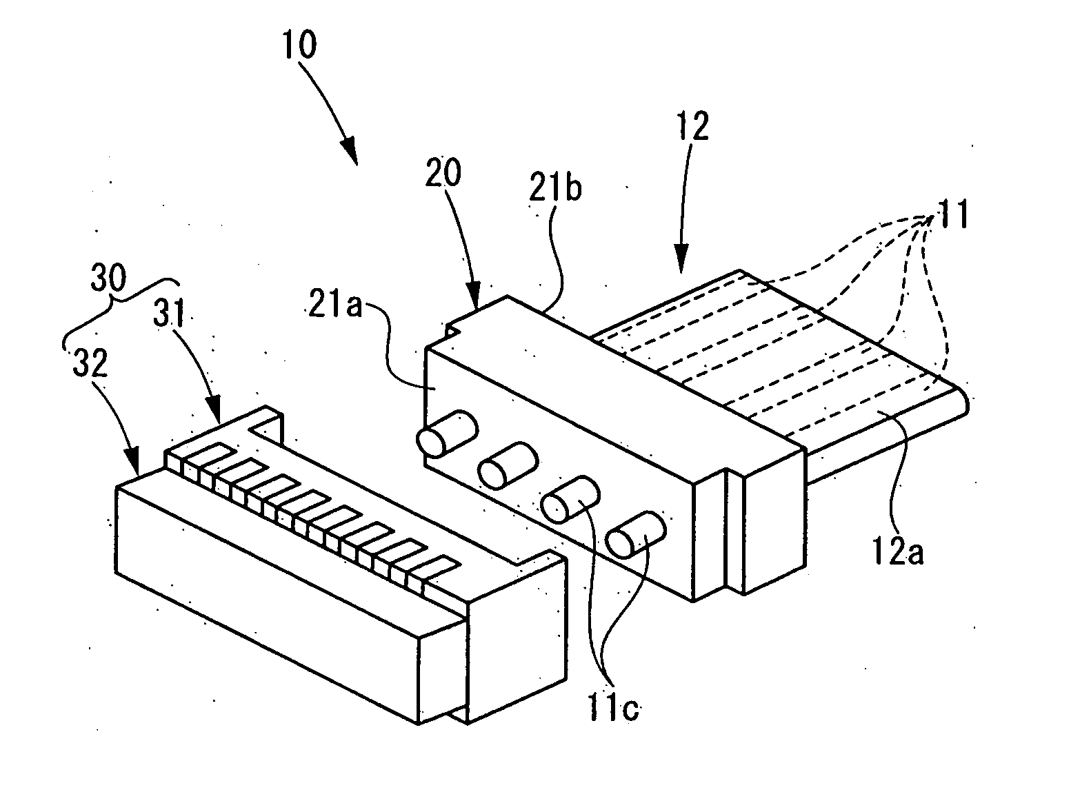
[0022]FIG. 1A is an exploded perspective view showing an embodiment of a photoelectric coupling assembly of the present invention, and FIG. 1B is a cross-sectional view of the same. This photoelectric coupling assembly 10 is used to couple optical fibers 11 with light-receiving / emitting elements 33, and includes a plug 20 and an optical head member 30 that can be fitted into each other. The plug 20 is provided with through-holes 22 that correspond to the guide holes 34 in the optical head member 30 and that allow the optical fibers 11 to pass through, and the distal ends 11a to protrude. The through-holes 22 are provided with guiding holes 22a for positioning the distal ends 11a of the optical fibers 11 and allowing them to be inserted to the guide holes 34. The optical fibers are held in the plug 20 such that the distal ends 11a of the optical fibers 11 are passed through guiding holes 22a and protruding portions 11c of the optical fibers 11 extend from a distal end surface 21a of ...
PUM
 Abstract
Description
Claims
Application Information
 - R&D
- Intellectual Property
- Life Sciences
- Materials
- Tech Scout
- Unparalleled Data Quality
- Higher Quality Content
- 60% Fewer Hallucinations
Browse by: Latest US Patents, China's latest patents, Technical Efficacy Thesaurus, Application Domain, Technology Topic, Popular Technical Reports.
© 2025 PatSnap. All rights reserved.Legal|Privacy policy|Modern Slavery Act Transparency Statement|Sitemap|About US| Contact US: help@patsnap.com