
T-nut for hopper feeding having a projection

a technology of hopper feeding and t-nut, which is applied in the field of t-nut, can solve problems such as overlaying

Active Publication Date: 2007-02-08
NAGAYAMA ELECTRONICS IND
View PDF24 Cites 2 Cited by
  • Summary
  • Abstract
  • Description
  • Claims
  • Application Information

AI Technical Summary

Benefits of technology

[0068] wherein the projection provided on the front supply periphery 50a or the back supply periphery 50b of one T-nut is engaged with the projection provided on the back supply periphery 50a or the front supply periphery 50b of another T-nut, which is next to the one T-nut in the supply track, so as to prevent the front supply periphery or the back supply periphery of the one T-nut from overlaying on the back supply periphery or the front supply periphery of the another T-nut, and so as to enable the T-nut to be almost perfectly buried into the fixing material with the flange being parallel to the surface of the fixing material.

Problems solved by technology

However, if the guide rails 10, 11 of C-shape have a broad space to accept the flange portion and the t-nut is slid on the feeding track 9 as shown in FIG. 33, there may occur the overlaying problems, even if the flange portion of the t-nut are almost octagonal, as shown in FIGS. 32 and 33.

Method used


Image

  • T-nut for hopper feeding having a projection
  • T-nut for hopper feeding having a projection
  • T-nut for hopper feeding having a projection

Examples


Embodiment Construction

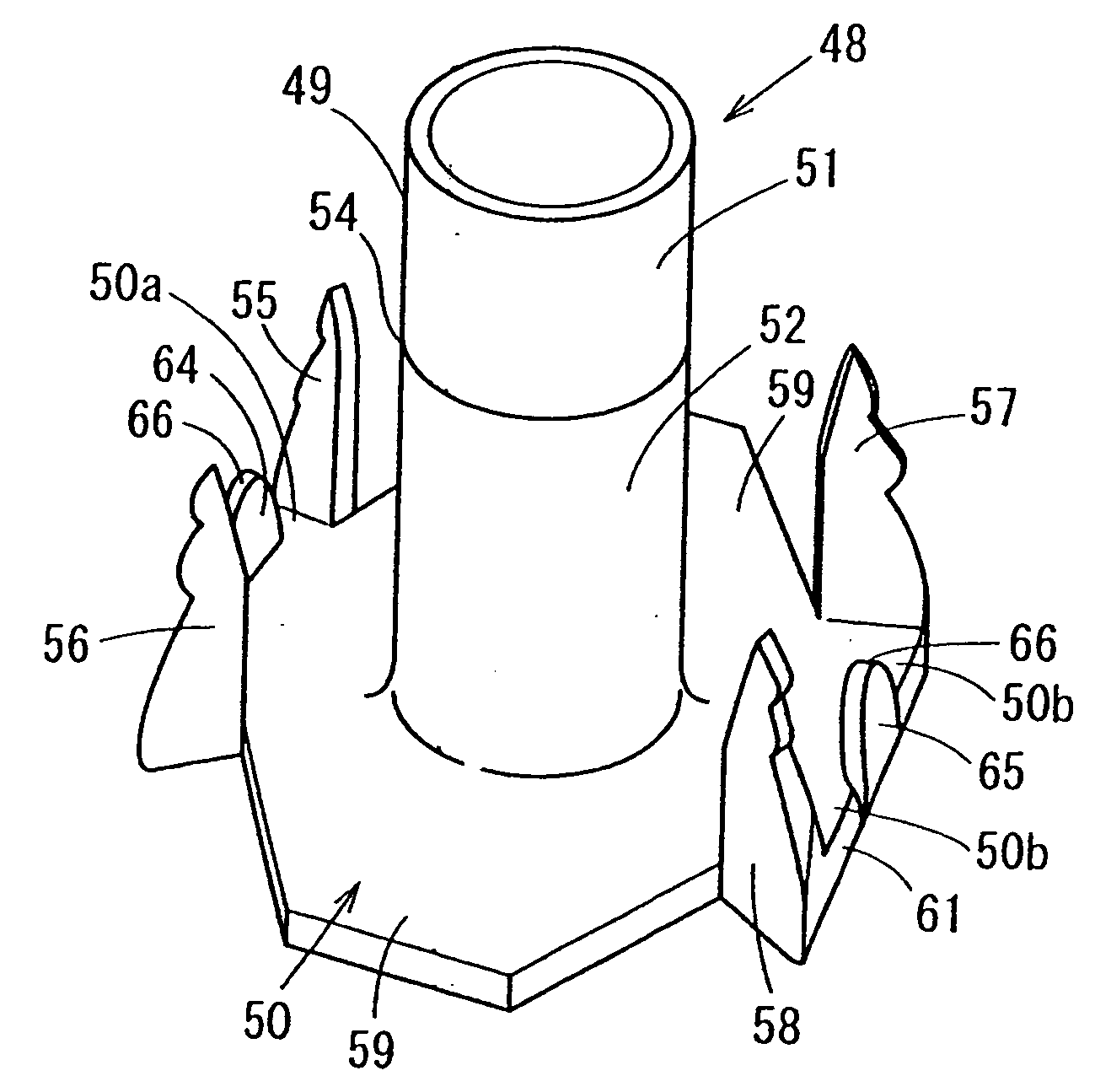
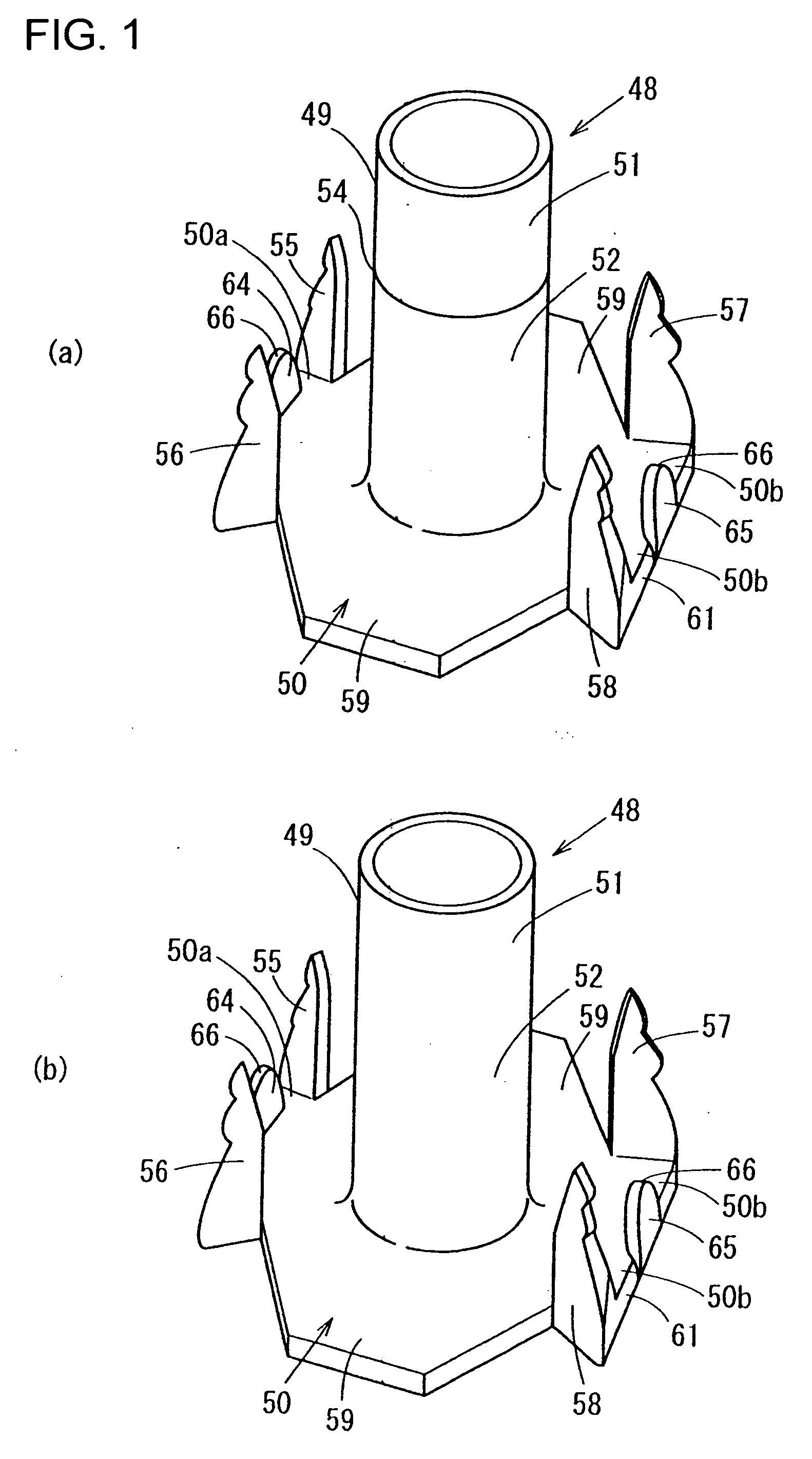
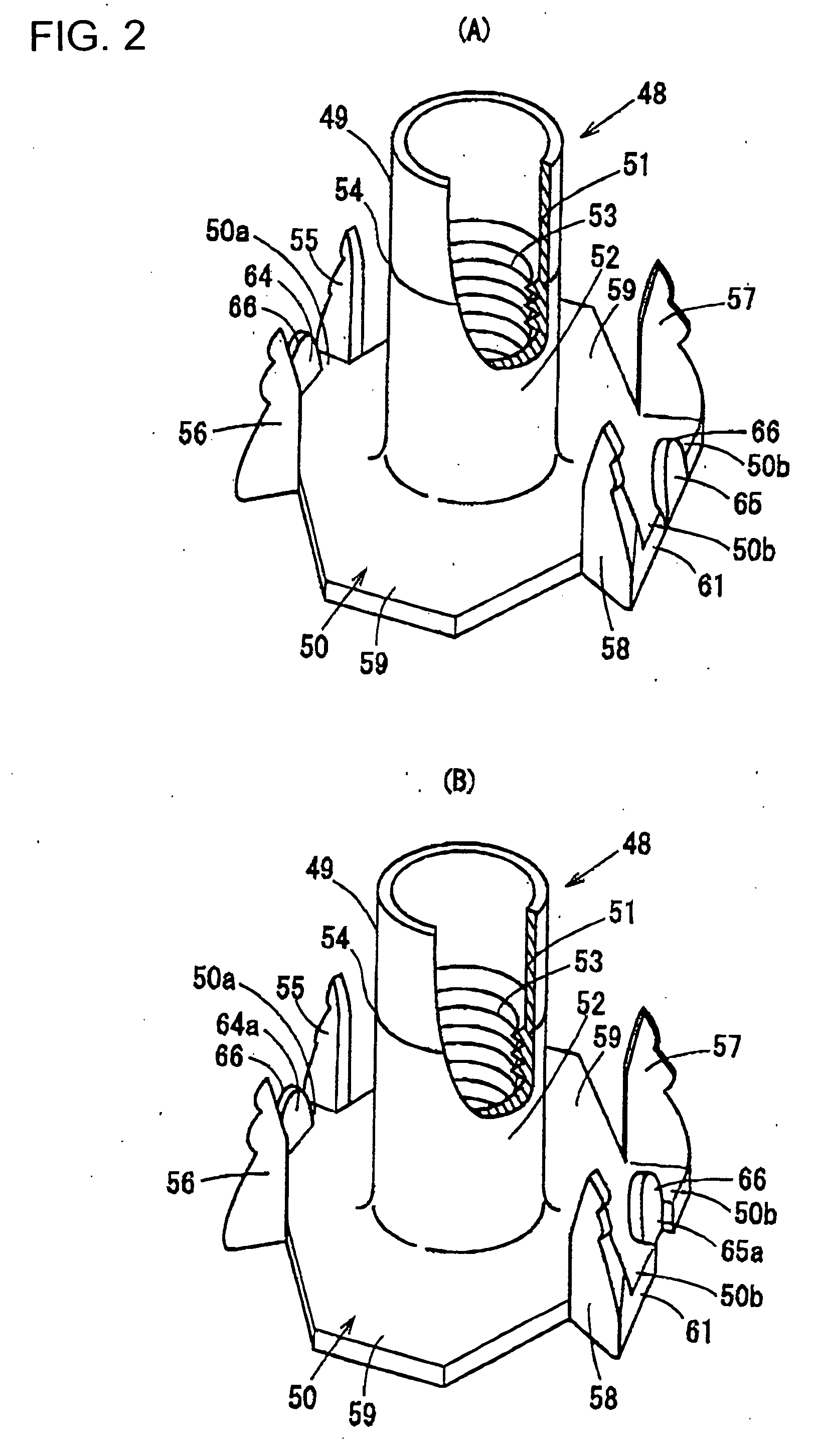
[0110] The t-nut of the present invention is described in detail based on preferred embodiments is as follows. FIGS. 1 to 6 show a first embodiment of the t-nut 48 of the present invention.

[0111] The t-nut can be obtained integrally formed by, for example, processing a metal plate of a ferric series, so as to have a shank portion 49 and a flanged portion 50. The shank portion 49 has a first end and a second end. The flange portion 50 is projected horizontally and outwardly from the first end of the shank portion 49.

[0112] The shank portion 49, having a first end and a second end, is shaped into a cylindrical tube, so as to have a hollow portion therein. The shank portion 49 closer to the second end is pressed to form a caulking portion 51. On the other hand, the shank portion 49 closer to the first end, that is a base portion, is formed to have a female screw on the inside surface of the cylindrical tube of the shank portion 49. Thus, the inner surface of the base portion has a fe...


PUM


Abstract

The present invention is to avoid the flange portion of a T-nut of from overlapping the portion between the claws of another T-nut, while the T-nut is supplied on a supply track provided on a nut applying machine, and also to engage the projections formed between the claws into a fixing material when the T-nut is knocked into the fixing material. There is provided a T-nut formed of a metal material in an integrated manner, having a shank portion 49 and an octagonal or almost octagonal flange portion 50, and two pairs of claws 55 to 58. The shank portion 49 has a caulking portion 51 and a female screw portion 52. The caulking portion 51 is formed thinner than the female screw portion 52. Projections 64, 65 are provided between each of the pairs of claws, formed by bending convex portions integrally formed with the flange portion 50 toward the second end of the shank portion 49.

Description

[0001] This application is a divisional application of prior application Ser. No. 10 / 860,015 filed on Jun. 4, 2004.FIELD OF THE INVENTION [0002] The present invention relates to a t-nut, and more specifically to a t-nut, or “counter bore hopper feed t-nut” having a caulking portion formed on a shank portion shaped into a cylindrical tube form. A female screw may be formed on the inside surface of the shank portion besides than the caulking portion. Several claws are formed on a flange portion thereof, which is horizontally projected outside from one end of the shank portion. RELATED ART [0003]FIG. 33 is a perspective view of a conventional t-nut which relates to the present inventions. [0004]FIG. 33 shows a t-nut 1 which is integrally formed of a metal material. The t-nut has a shank portion 2 having a first end and a second end. The t-nut also has a flange portion 3 horizontally projected outwardly from the first end of the shank portion 2. The shank portion 2 is shaped into a cyli...

Claims


Application Information

Patent Timeline
Patent Type & Authority Applications(United States)
IPC IPC(8): F16B37/04
CPCF16B37/048
Inventor NAGAYAMA, YUTAKA
Owner NAGAYAMA ELECTRONICS IND
Learn More