Bus bar

Active Publication Date: 2019-11-07
APTIV TECH LTD
View PDF5 Cites 2 Cited by
  • Summary
  • Abstract
  • Description
  • Claims
  • Application Information

AI Technical Summary

Benefits of technology

[0003]Techniques are described herein to provide an improved bus bar that assures that an attached fuse does

Problems solved by technology

A problem occurs due to the fact that the bus bar made of metal and the housing made of plastic have different thermal expansion coefficients.
Since the fuse is mechanically wea

Method used


Image

  • Bus bar
  • Bus bar
  • Bus bar

Examples


first embodiment

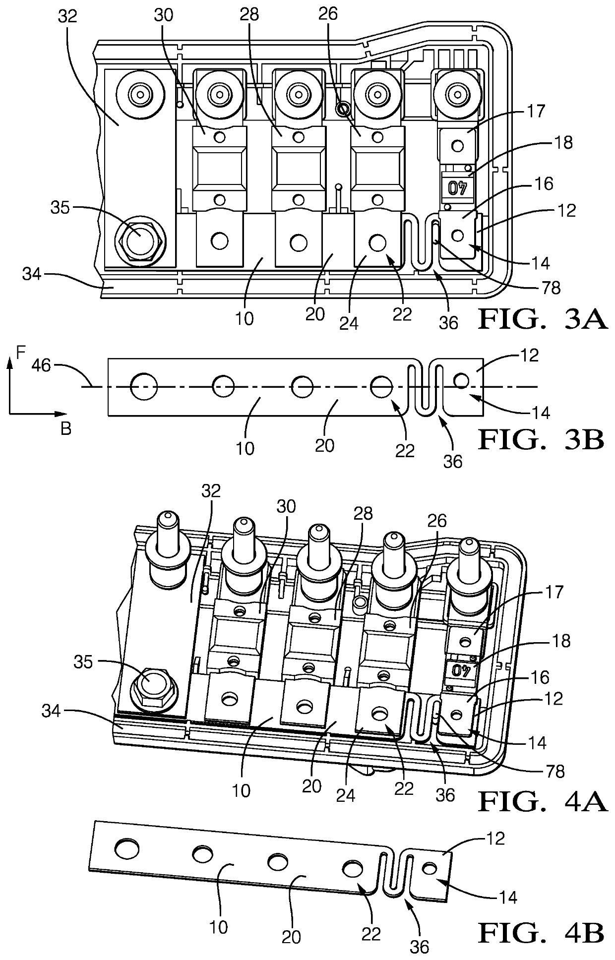
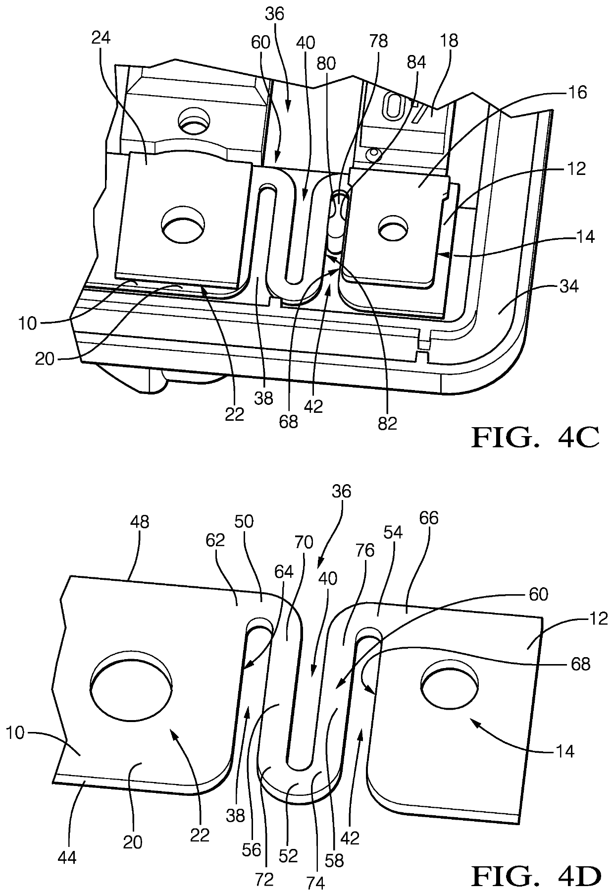
[0064]In FIGS. 3A to 4D, a straight bus bar 10 according to the invention is shown. The bus bar 10 comprises a rigid first portion 12 with a first contact surface 14 that is connected to a first end 16 of a first fuse 18 (FIGS. 3A and 4A) and a rigid second portion 20 with a second contact surface 22 that is connected to a first end 24 of a second fuse 26. A third fuse 28, fourth fuse 30 and fifth fuse 32 are also connected to the bus bar 10 at their respective first ends.

[0065]The bus bar 10 is mechanically connected to a housing 34 via a screw 35. The housing 34 is made of a non-conductive material with a higher thermal expansion coefficient than the material of the bus bar 10, e.g. plastic. Thus, when the housing 34 and the bus bar 10 warm up due to a temperature rise around the bus bar 10 and the housing 34, they both expand in an axial direction i.e. the main direction B of the bus bar (FIG. 3B), and a lateral direction, i.e. the main direction F of the fuses. However, the bus ...

second embodiment

[0070]FIG. 5A to 5C depict a bus bar 110 according to the invention. The bus bar 110 has a rigid first portion 112 and a rigid second portion 120 which are connected to each other by a resilient compensation portion 136. The resilient compensation portion comprises a first lateral recess 138 extending from a first side surface 144 into the bus bar 110 further than a centerline 146 until only a first web portion 150 remains at an end of the lateral recess 138. The resilient compensation portion also comprises a second lateral recess 140 extending from a second side surface 148 parallel to the first lateral recess 138 further than the centerline 146 until only a second web portion 152 remains at the end of the lateral recess 140.

[0071]The lateral recesses 138 and 140 are spaced from each other in an axial direction so that a lateral web portion 156 is formed between the first lateral recess 138 and the second lateral recess 140. The lateral web portion 156 has a similar width than the...

third embodiment

[0074]FIG. 6A to 6C depict a bus bar 210 according to the invention. The bus bar 210 has a rigid first portion 212 and a rigid second portion 220 which are connected to each other by a resilient compensation portion 236.

[0075]The resilient compensation portion 236 comprises four lateral recesses, a first lateral recess 238, a second lateral recess 240, a third lateral recess 242 and a fourth lateral recess 243. The first lateral recess 238 extends from a first side surface 244 into the bus bar 210 shorter than to a centerline 246. The second lateral recess 240 extends from a second side surface 248 in the direction of the first lateral recess 238 towards the first lateral recess 238 into the bus bar 210 shorter than to the centerline 246. The first lateral recess 238 and the second lateral recess 240 form a first web portion 250 that remains at the centerline 246 between the first lateral recess 238 and the second lateral recess 240 in a lateral direction. The first lateral recess 2...


PUM


Abstract

A straight bus bar includes an axial direction and having a rigid first portion with a first contact surface connectable to a first fuse, an axially spaced rigid second portion with a second contact surface connectable to a second fuse, and a connecting portion electrically connecting the first portion and the second portion. The connecting portion is a resilient compensation portion having at least two lateral recesses extending from opposite sides into the bus bar making the connecting portion elastically bendable to allow a relative axial movement of the first and second portions when an axial force is applied to the bus bar.

Description

TECHNICAL FIELD OF INVENTION[0001]This disclosure generally relates to a straight bus bar defining an axial direction, and more particularly to a straight bus bar that is used in a vehicleBACKGROUND OF INVENTION[0002]A straight bus bar can be used in a vehicle's electrical system to electrically connect multiple midi fuses to it. In an internally known design, the bus bar is made of rigid conductive metal and is mechanically and electrically connected to one end of a fuse and the other end of the fuse is mechanically connected to a housing made of non-conductive plastic. The main direction of the fuse is arranged perpendicular to the axial direction of the bus bar. When the vehicle is exposed to hot or cold climate conditions, the bus bar and the housing will thermally expand or contract due to a change of temperature. A problem occurs due to the fact that the bus bar made of metal and the housing made of plastic have different thermal expansion coefficients. When the bus bar and th...

Claims


Application Information

Patent Timeline
IPC IPC(8): B60R16/02H02B1/20H02G5/00H01H85/044
CPCH02B1/20H01H2085/0555H01H85/044B60R16/02H02G5/002H01B5/002H01B5/02H01R25/161H01H85/02H01H85/20H01H85/2045H01H2085/2075H01H2085/208
Inventor KOT, PAWELHEBDA, DARIUSZBEBENEK, DAWIDSTEFANSKI, KONRAD
Owner APTIV TECH LTD
Why Eureka
Try Eureka