Vapor chamber

a technology of vapor chamber and heat sink, which is applied in the direction of reinforcement means, spacing means, lighting and heating apparatus, etc., can solve the problems of vapor chambers that cannot withstand too much external force, vapor chambers that tend to be fragile and cannot be sealed or welded around the hole break, and parts of the pla

Active Publication Date: 2019-07-25
COOLER MASTER CO LTD
View PDF0 Cites 6 Cited by
  • Summary
  • Abstract
  • Description
  • Claims
  • Application Information

AI Technical Summary

Benefits of technology

[0006]The main objective of the present invention is to provide a vapor chamber that may not be broken when fixed by screws.

Problems solved by technology

Because the plates are thin (and thus tend to be weak in their mechanical strengths), and because the pressure difference between inside and outside of the chamber is too much, the vapor chamber tends to be fragile and cannot withstand too much external force.
For example, because some holes of the vapor chamber are made through stamping or drilling after two plates are sealed, force or stress generated by the stamping or drilling might make the sealed or welded part around the hole break; or if a screw mounted through one of the interior holes as described above has a head larger than the joined portion around the hole, the screw's head may abut and thus crush a portion of the plate that forms the vapor chamber.
This may result in a crack on the plate, which can break the vacuum and cause the vapor chamber to fail.

Method used


Image

  • Vapor chamber
  • Vapor chamber
  • Vapor chamber

Examples


first embodiment

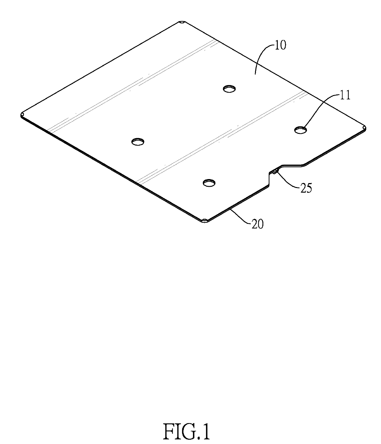
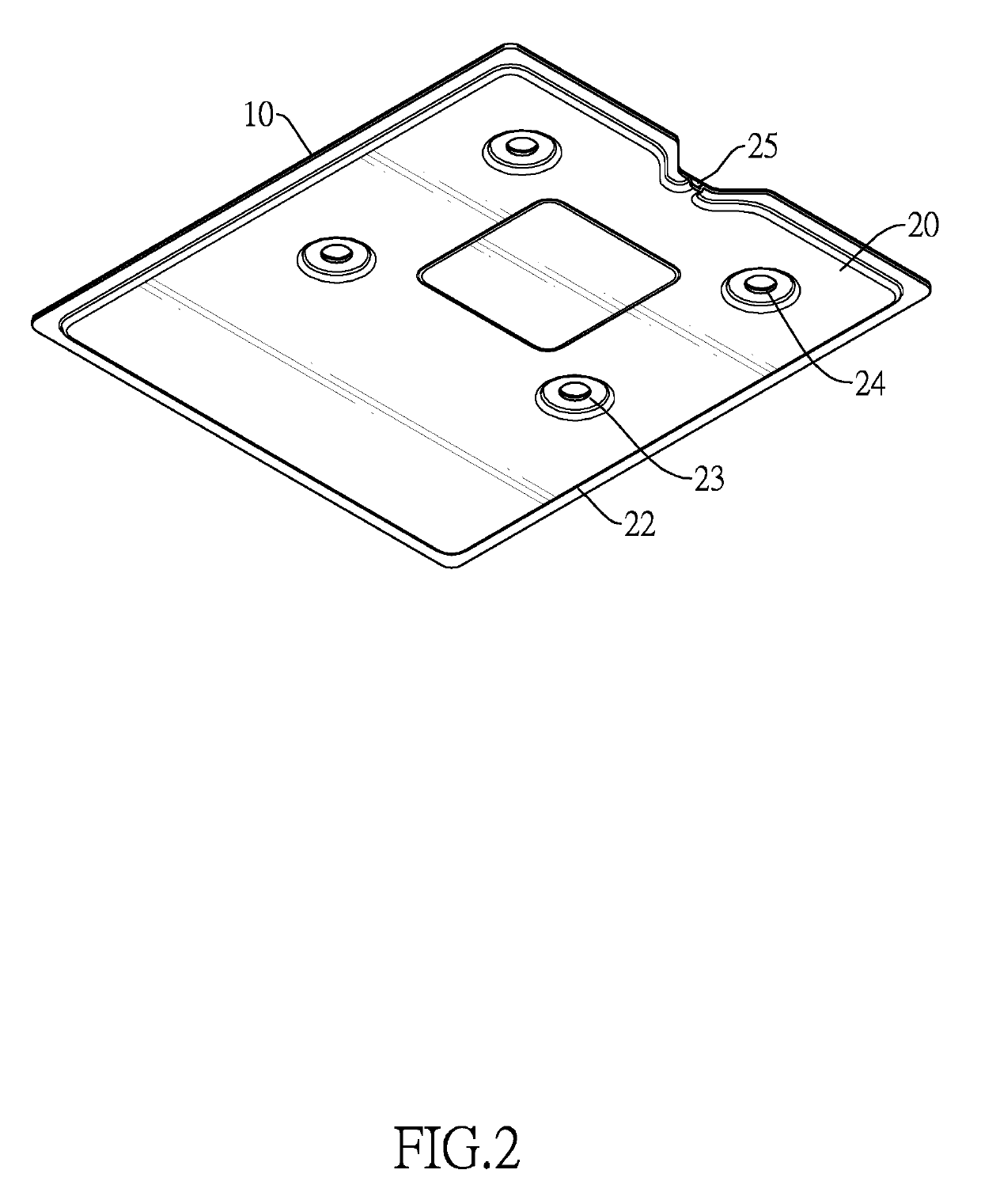
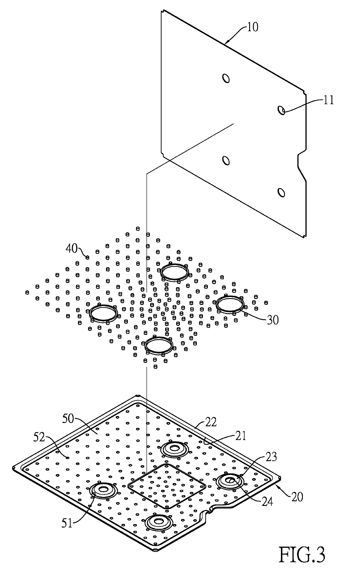
[0020]With reference to FIGS. 1 to 3, a vapor chamber in accordance with the present invention may comprise a first plate 10, a second plate 20, at least one ring structure 30, a plurality of spacers 40, and at least one first capillary structure layer 50.

[0021]In this embodiment, a contour of the first plate 10 and a contour of the second plate 20 may match each other or may be the same, and may be joined and sealed together, for example, by welding. The first plate 10 may be flat and may comprise one or more holes 11. The second plate 20 may comprise a cavity portion 21, a margin portion 22, one or more annular protrusions 23 located interiorly within the cavity portion 21 and protruding toward the first plate 10, and one or more holes 24. Each annular protrusion 23 may surround and encircle a respective one of the holes 24. In other words, each one of the holes 24 is formed through a respective one of the annular protrusions 23. An opening of the cavity portion 21 of the second p...

third embodiment

[0044]Then please refer to FIG. 10. A vapor chamber in accordance with the present invention is provided. One of the differences is that, the vapor chamber may have two first capillary structure layers 50B. One of the first capillary structure layers 50B may be attached to the surface of the first plate 10 facing toward the second plate 20, and the other first capillary structure layer 50B may be attached to the bottom surface of the cavity portion 21 of the second plate 20 and may be further on a side wall of the cavity portion 21.

[0045]Consequently, the vapor chamber in accordance with the present invention is sealed by the ring structures 30. With such structures, the chamber can keep sealed even when heads of screws mounted through the holes 11, 24 for fixing the vapor chamber are larger and oppress the margins of the holes 11, 24 or even when the vapor chamber undergoes the stamping or drilling process. Besides, with the spacers 40 scattered around inside the chamber, a mechani...


PUM


Abstract

A vapor chamber has a first plate, a second plate, at least one ring structure, and a chamber. The first plate and the second plate have holes communicating with each other. The second plate has a cavity portion concaved away from the first plate. The ring structure is in the cavity portion and encloses the holes. The chamber is formed between the first plate and the second plate. A capillary structure layer and a working liquid are in the chamber. Therefore, even when either of the first and second plates is broken by heads of screws mounted through the holes, which are larger and oppress the margins of the holes, or even when either of the first and second plates is broken during forming of the holes via stamping or drilling, the chamber always remain sealed.

Description

CROSS-REFERENCE TO RELATED APPLICATIONS[0001]This application is based upon and claims priority under 35 U.S.C. 119 from U.S. Provisional Application No. 62 / 620,748 filed on Jan. 23, 2018, which is hereby specifically incorporated herein by this reference thereto.BACKGROUND OF THE INVENTION1. Field of the Invention[0002]The present invention relates to a heat dissipation component in a heat sink, particularly a vapor chamber.2. Description of the Prior Arts[0003]Vapor chambers are widely used because they usually do not occupy much space, and yet can efficiently and evenly dissipate heat from a heat source of a very small area to a much larger area or surface. A conventional vapor chamber comprises two narrowly spaced apart plates joined together at their edges (typically by welding), with a thin internal chamber space formed between the two plates surrounded and sealed by the edges. Before the internal chamber space is completely sealed, thereby forming a chamber, a working liquid ...

Claims


Application Information

Patent Timeline
Patent Type & Authority Applications(United States)
IPC IPC(8): F28D15/04F28F3/12
CPCF28D15/046F28F3/12F28F2225/04F28D15/04F28F3/10F28D15/0233F28D15/0275F28F2240/00F28F2275/06H01L23/427
Inventor CHENG, JEN-CHIH
Owner COOLER MASTER CO LTD
Why Eureka
Try Eureka