
Microsurgical robot system

a robot system and micro-scopy technology, applied in the field of micro-scopy robot systems, can solve the problems of limited clinical application value, difficult to achieve precise localization of brain pathology and neural structures, and surgeons currently have no effective way to use imri data to enhance the precision and dexterity of surgery, so as to facilitate safety and tool changing, the effect of reducing patient risk

Inactive Publication Date: 2007-02-08
DEERFIELD IMAGING INC
View PDF99 Cites 214 Cited by
  • Summary
  • Abstract
  • Description
  • Claims
  • Application Information

AI Technical Summary

Benefits of technology

[0034] achieves true image-guided surgery by registration of iMRI fiducials registered by a digitizer on the robot base, and updating this positional data with information from encoders in the robot joints. This enhances the surgeon's situational awareness by constantly updating the position of the tool tips in relation to the surgical target; and
[0077] The system has been created de novo for the specific purpose of performing microsurgery and stereotaxy. This includes standard techniques such as micro-dissection, thermo-coagulation, and fine suturing. Procedures such as tumor resection and aneurysm clipping are possible. The design of the robot is inclusive and versatile however, and is ideal in other microsurgical specialties such as ophthalmology. The fine dexterity and low payload of the end-effectors precludes their use in gross manipulation of tissue and bone, as these tasks are more readily suited to humans. Other unique features include MRI-compatibility as tested at 3 T, and a mechanical navigation system. This makes the system the first truly image-guided surgical robot. It is also the only surgical robot with eight-DOF per arm (including tool actuation). Although this is significantly less than human DOF, it exceeds the six-DOF required to position a tool precisely in space and then orient it in the desired plane. Unnecessary DOF result in cumulative instability while insufficient DOF result in limited positioning of the manipulator. Surgeons performing microsurgery will instinctively eliminate redundant DOF by fixing their shoulder and elbow joints, but retain adequate dexterity in the hands and wrists to perform delicate microsurgery. The manipulators were designed to have the necessary dexterity to perform these same tasks.

Problems solved by technology

They also have physiological limits to their precision, tactile sensibility and stamina.
Furthermore, the precise localization of brain pathology and neural structures is often difficult to achieve during surgery due to brain shifts and deformations as the operation progresses.
While Intra-operative Magnetic Resonance Imaging (iMRI) has been used to monitor brain deformations, the surgeon currently has no effective way to use the iMRI data to enhance the precision and dexterity of surgery.
They are compelled to rely on old techniques, and do not take advantage of these exquisite, updated images.
Consequently, the quality of the surgery and outcomes is variable, and too often sub-optimal.
Unfortunately, there are no surgical robots that provide the surgeon with an ambidextrous and precise surgical system that uses updated iMRI patient data to achieve accurate image-guided surgery.
In addition, there is no surgical robot with force sensing technology that is compatible with MRI systems.
MIS robots are not suitable for neurosurgery since they require a portal in the body and lack the required dexterity and ability to reposition to different surgical worksites.
Furthermore, neither system is MR compatible nor is there any force feedback capability.
Again, they lack the dexterity, MR compatibility and force sensing needed for neurosurgery.
Robots designed for neurosurgical applications are generally restricted to positioning and holding instruments for simple procedures such as stereotactic biopsies.
Progress in developing this system was limited by the inability to rapidly render updated 3D brain images in the operating room.
Again, the systems have only one robotic arm and cannot emulate a human surgeon.
Although RAMS has the required dexterity, it is still a single arm system lacking the ability to reposition itself over a large worksite.
It is also not MR compatible and has no direct force feedback sensing capability and is not image-guided.
The limited capabilities of the device caused it to fall into disuse.

Method used


Image

  • Microsurgical robot system
  • Microsurgical robot system
  • Microsurgical robot system

Examples


Embodiment Construction

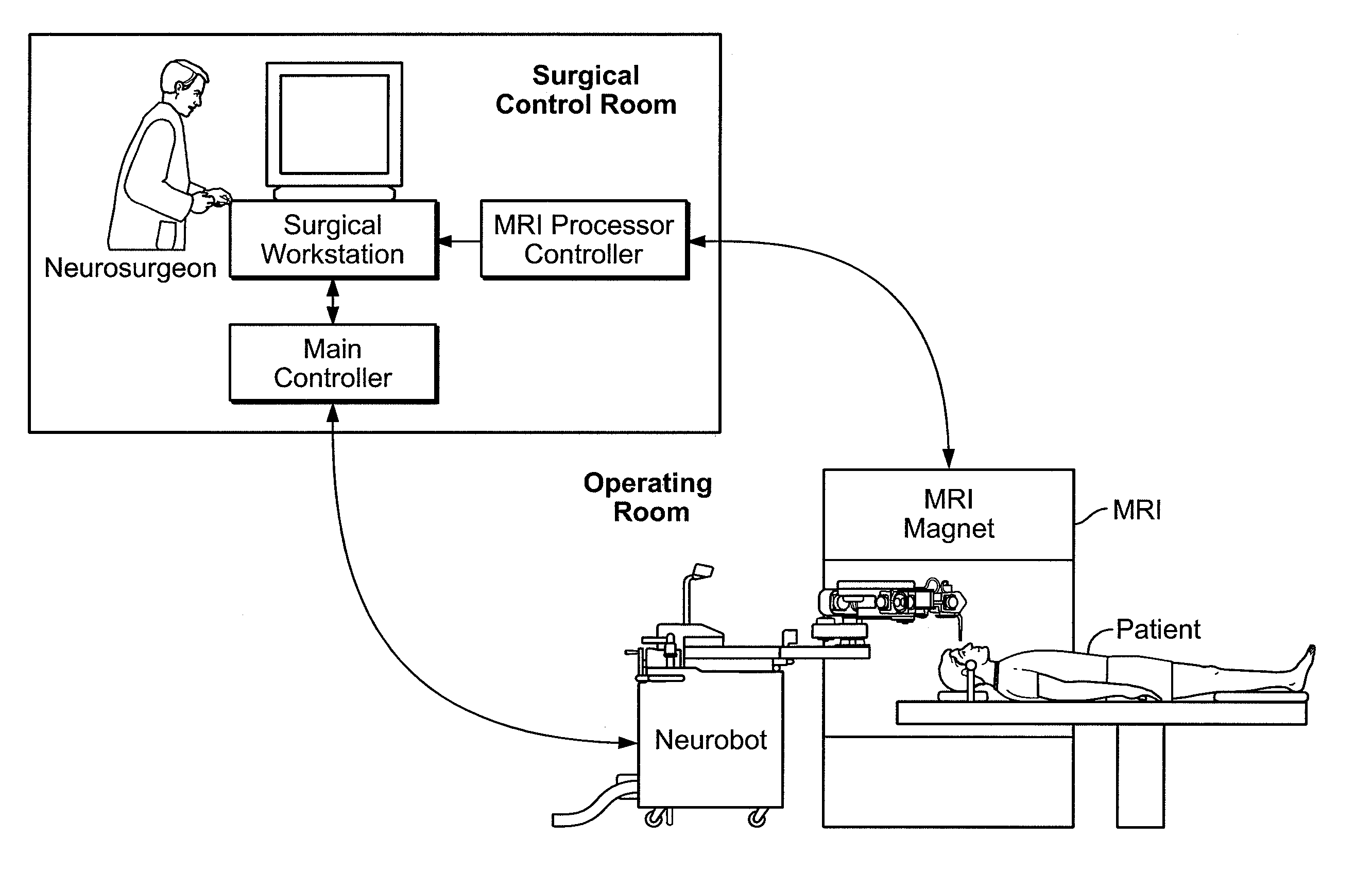
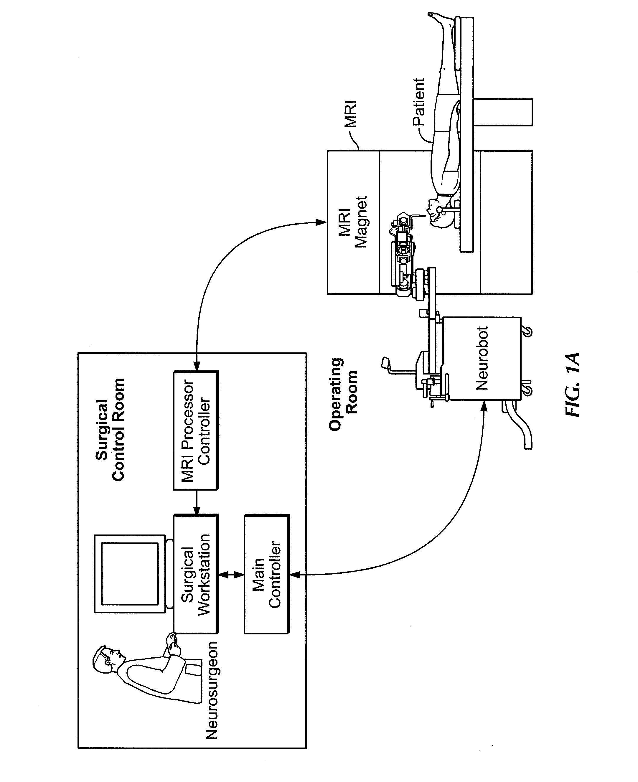
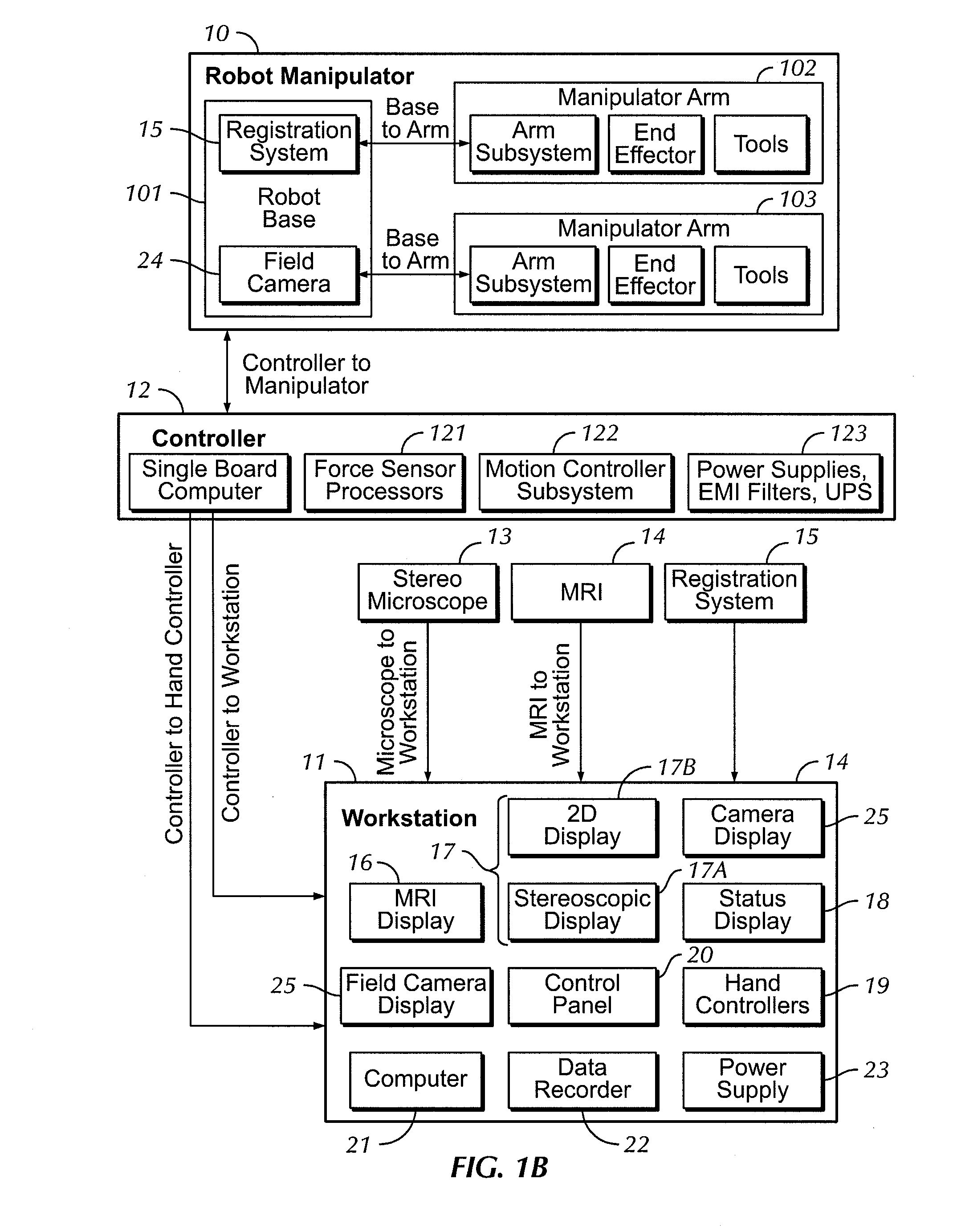
[0096] Further details of the above generally described system are shown in the attached drawings 1 through 17.

[0097] An overview of the system is shown in FIG. 1B which comprises a robot manipulator 10, a work station 11 and a controller 12 which communicates between the robot manipulator and the work station. As inputs to the work station is also provided a stereo microscope 13, an MRI imaging system 14 and a registration system 15.

[0098] The work station includes a number of displays including at first display 16 for the MRI image, a second display 17 for the microscope image and a third display 18 for the system status. Further the work station includes two hand controllers schematically indicated at 19 and an input interface 20 allowing the surgeon to control the systems from the work station while reviewing the displays. The work station further includes a computer or processor 21, a data recording system 22 and a power supply 23.

[0099] The display 17 includes a stereoscopi...


PUM


Abstract

A robot system for use in surgical procedures has two movable arms each carried on a wheeled base with each arm having a six of degrees of freedom of movement and an end effector which can be rolled about its axis and an actuator which can slide along the axis for operating different tools adapted to be supported by the effector. Each end effector including optical force sensors for detecting forces applied to the tool by engagement with the part of the patient. A microscope is located at a position for viewing the part of the patient. The position of the tool tip can be digitized relative to fiducial markers visible in an MRI experiment. The workstation and control system has a pair of hand-controllers simultaneously manipulated by an operator to control movement of a respective one or both of the arms. The image from the microscope is displayed on a monitor in 2D and stereoscopically on a microscope viewer. A second MRI display shows an image of the part of the patient the real-time location of the tool. The robot is MRI compatible and can be configured to operate within a closed magnet bore. The arms are driven about vertical and horizontal axes by piezoelectric motors.

Description

CROSS REFERENCES TO RELATED APPLICATIONS [0001] This patent application is a continuation of co-pending application Ser. No. 10 / 639,692 filed on Aug. 13, 2003, which claims priority to U.S. Provisional Patent Application No. 60 / 402,724 filed on Aug. 13, 2002; each of these applications is incorporated by reference in its entirety.BACKGROUND OF THE INVENTION [0002] Complication avoidance in microsurgery (neurosurgery, ophthalmology, otorhinolaryngology, limb and digit reattachment) is crucial, and minimizes patient morbidity and health care costs. Current operative techniques rely on human surgeons, who have variable skill and dexterity. They also have physiological limits to their precision, tactile sensibility and stamina. Furthermore, the precise localization of brain pathology and neural structures is often difficult to achieve during surgery due to brain shifts and deformations as the operation progresses. While Intra-operative Magnetic Resonance Imaging (iMRI) has been used to ...

Claims


Application Information

Patent Timeline
Patent Type & Authority Applications(United States)
IPC IPC(8): G05B19/418A61B19/00
CPCA61B19/22A61B2019/5287A61B19/5212A61B19/5223A61B19/5244A61B19/54A61B19/56A61B2017/00911A61B2019/2223A61B2019/223A61B2019/2234A61B2019/2242A61B2019/2269A61B2019/2288A61B2019/2292A61B2019/2296A61B2019/464A61B2019/502A61B2019/5236A61B2019/5259A61B19/2203A61B34/20A61B34/25A61B34/30A61B34/35A61B34/37A61B34/70A61B34/71A61B34/74A61B34/75A61B34/76A61B34/77A61B90/20A61B90/25A61B90/361A61B90/39A61B2034/102A61B2034/2059A61B2034/305A61B2090/064A61B2090/363A61B2090/374
Inventor SUTHERLAND, GARNETTE ROYLOUW, DEON FRANCOISMCBETH, PAUL BRADLEYFIELDING, TIMGREGORIS, DENNIS JOHN
Owner DEERFIELD IMAGING INC
Learn More