

Automatic or semi-automatic rifle
a semi-automatic and rifle technology, applied in the direction of breech mechanism, butt, weapons, etc., can solve the problems of encumbering the field removal and replacement of the barrel, and affecting the operation of the rifl
- Summary
- Abstract
- Description
- Claims
- Application Information
AI Technical Summary
Benefits of technology
Problems solved by technology
Method used
Image

Examples
Embodiment Construction
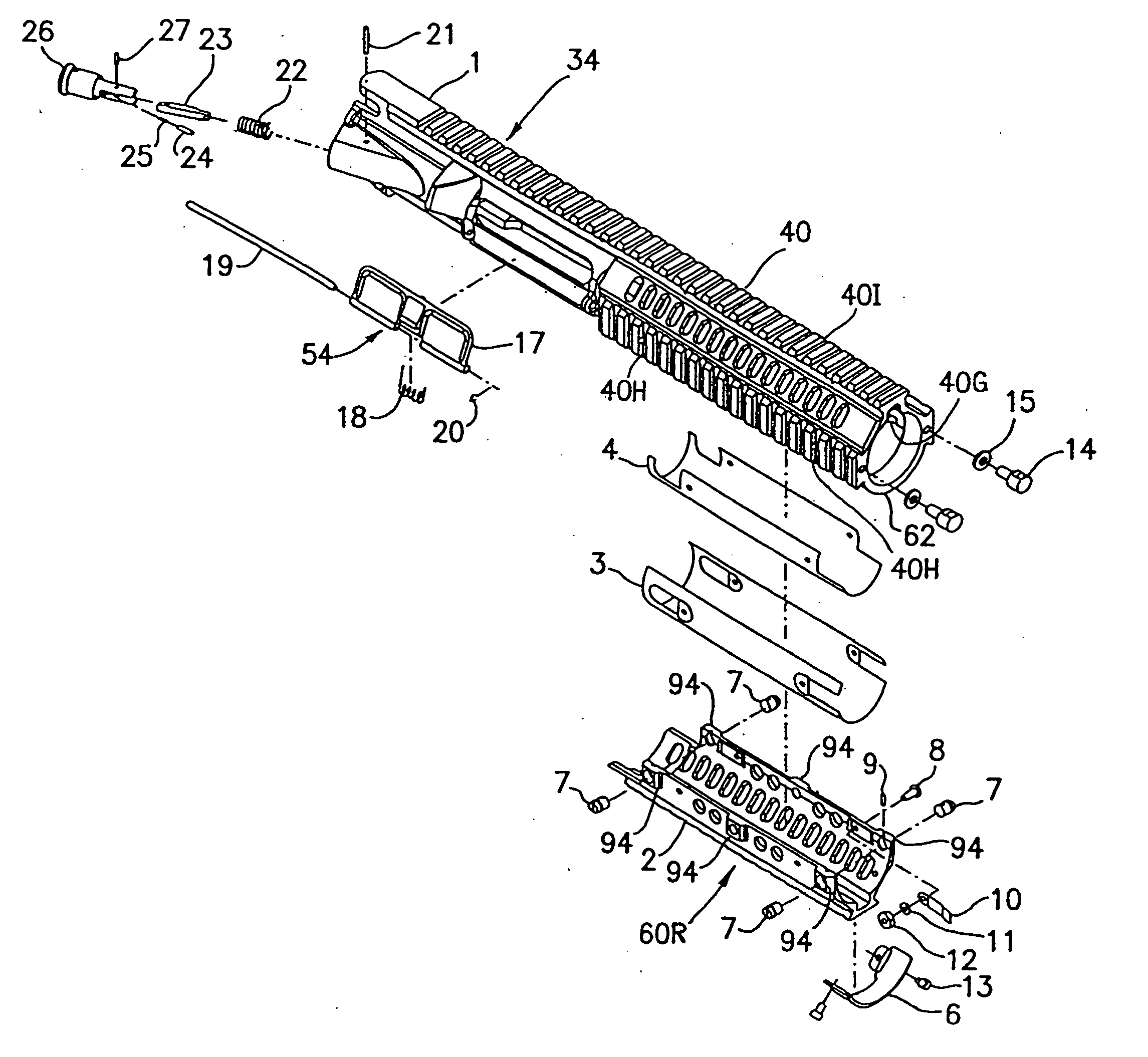
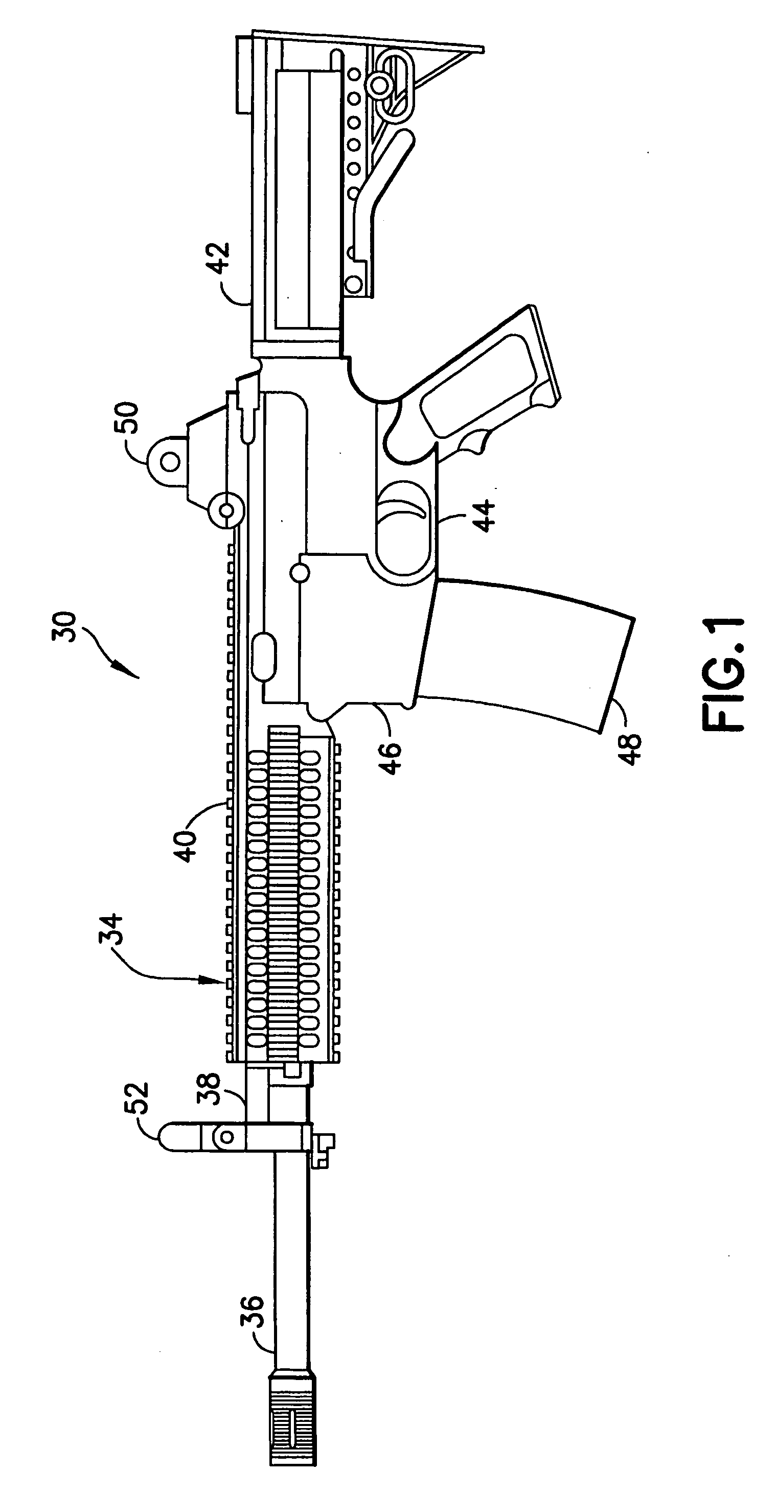
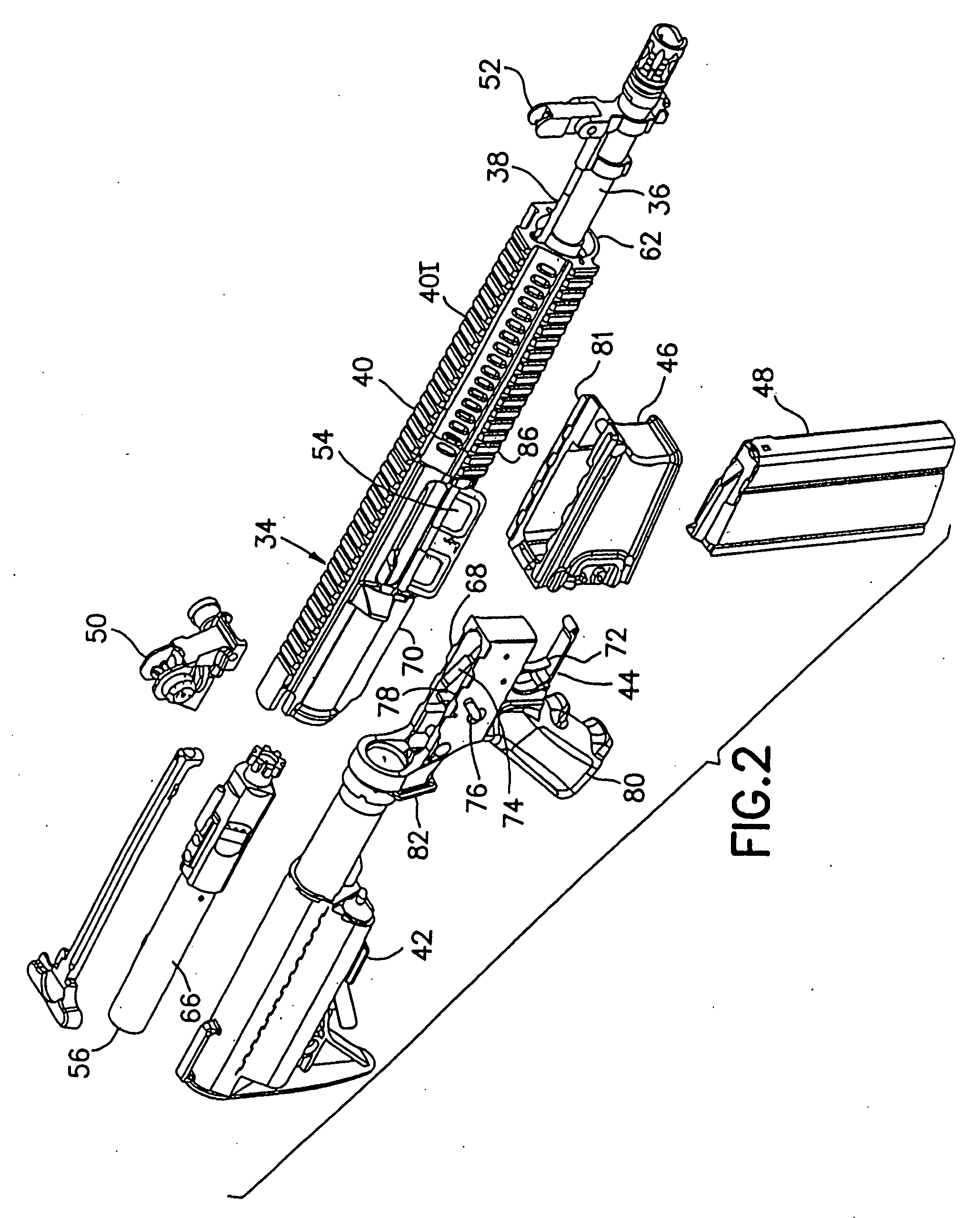
[0006] In accordance with one exemplary embodiment, an M-4 firearm is provided. The M-4 type firearm has a receiver with an integral hand guard and a barrel. The barrel is connected to the receiver. The hand guard extends over and surrounds the barrel. A removable hand guard is attached to the receiver by an attachment that stably holds the removable hand guard to the receiver. The attachment is arranged for allowing detachment and removal of the removable hand guard from the receiver without removal of fasteners.
[0007] In accordance with another exemplary embodiment a semi-automatic rifle is provided. The rifle has a receiver, a barrel, a removable accesory device mounting rail, and a quick release lock. The receiver has an integral hand guard portion. The barrel is removably connected to the receiver. The removable accessory device mounting rail is removably connected to the receiver. The hand guard extends over and surrounds the barrel. The rail has another hand guard portion ma...
PUM
 Abstract
Description
Claims
Application Information