Puncture adaptor, ultrasonic probe for puncture, ultrasonic diagnostic apparatus for puncture, method for detecting angle of puncture needle
a technology of ultrasonic probe and adaptor, which is applied in the field of puncture adaptor, ultrasonic probe for puncture, ultrasonic diagnostic apparatus for puncture, method for detecting the angle of the puncture needle, etc., can solve the problems of increasing the number of cables adversely affecting the operability, requiring a new puncture connector, and affecting the operability of operation
- Summary
- Abstract
- Description
- Claims
- Application Information
AI Technical Summary
Benefits of technology
Problems solved by technology
Method used
Image

Examples
first exemplary embodiment
(First Exemplary Embodiment)
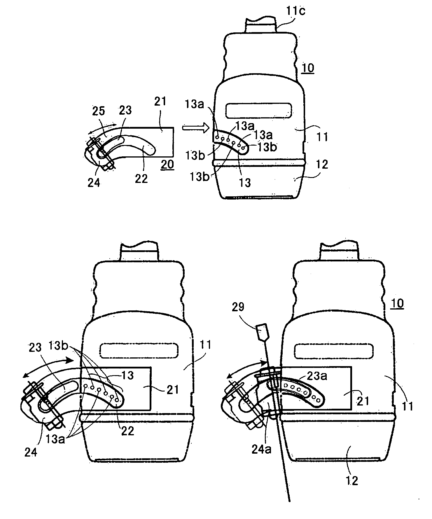
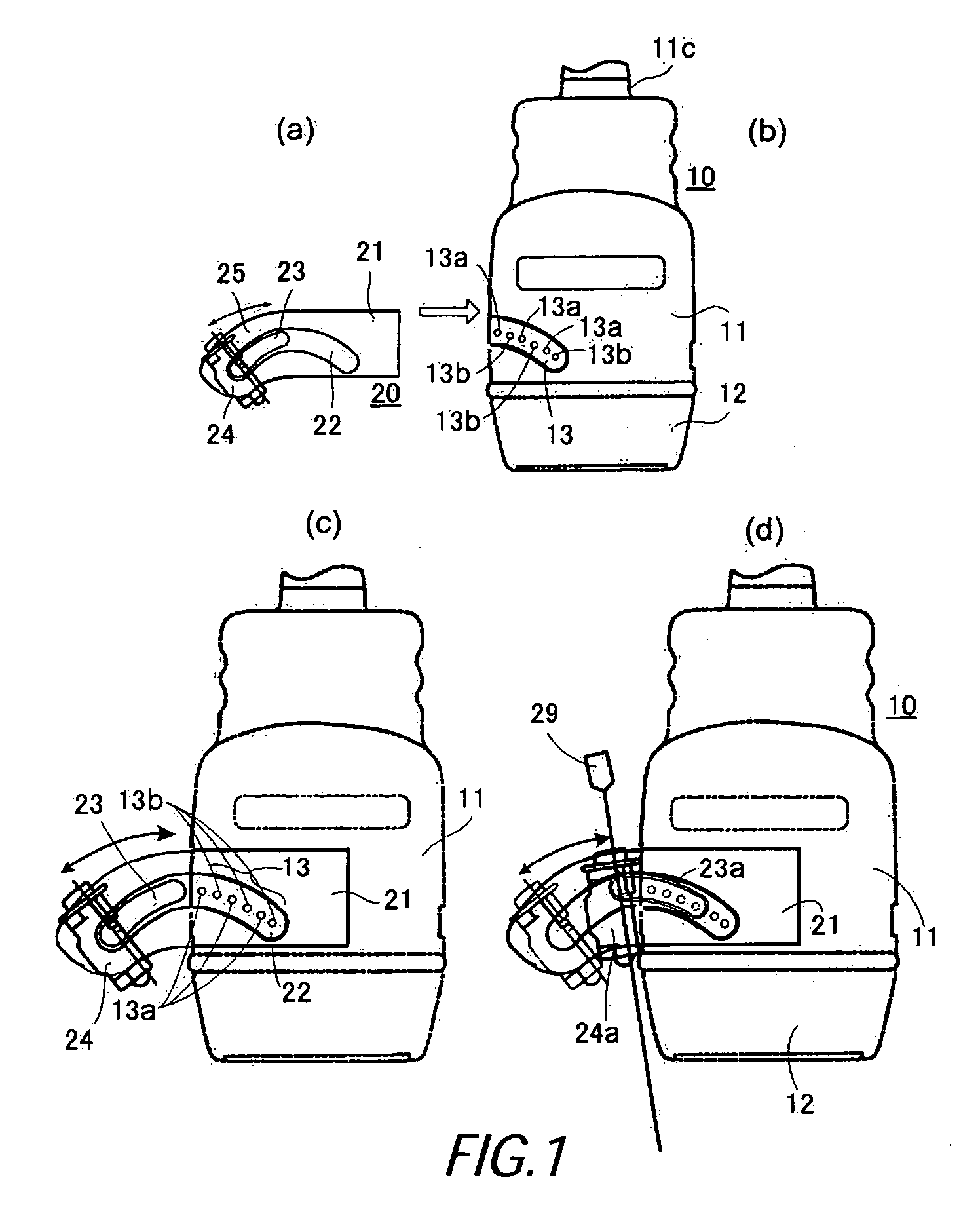
[0018] An ultrasonic probe 10 shown in FIG. 1 (b) includes a probe body 11 holding an ultrasonic transmit and receiving unit 12 having arrayed ultrasonic transducers, and an alternating photo sensor 13 including luminous elements 13a and light sensitive elements 13b. Lead wires of the luminous elements 13a and the light sensitive elements 13b are wired in a probe body 11. The wires are connected to a body of the ultrasonic diagnostic apparatus through a probe cable 11c with read wires of ultrasonic transducers.
[0019] As a slide opening part 22 of puncture adaptor 20 shown in FIG. 1 (a) is positioned opposite the photo sensor 13 of the probe body 11, a holder 21 of the puncture adaptor 20 holds the probe body 11, as shown in FIG. 1(c). A slider 23, having a reflective face facing the probe body 11, is fitted into a slide opening part 22 of the puncture adaptor 20, and a needle guide 24 is fastened at one end of the slider 23 by screws (not shown) to the s...
second exemplary embodiment
(Second Exemplary Embodiment)
[0030] In a second embodiment, as shown by FIG. 3, it is characteristic that a pattern having different degrees of reflection, for example a black and white stripe pattern, is provided on a probe body side of the slider 26. The pattern is detected by one pair of a luminance element 15a and a sensitive element 15b provided on the probe body 11. In the explanation of this exemplary embodiment, explanations of similarities with the first exemplary embodiment will be skipped, and differences will be mainly explained.
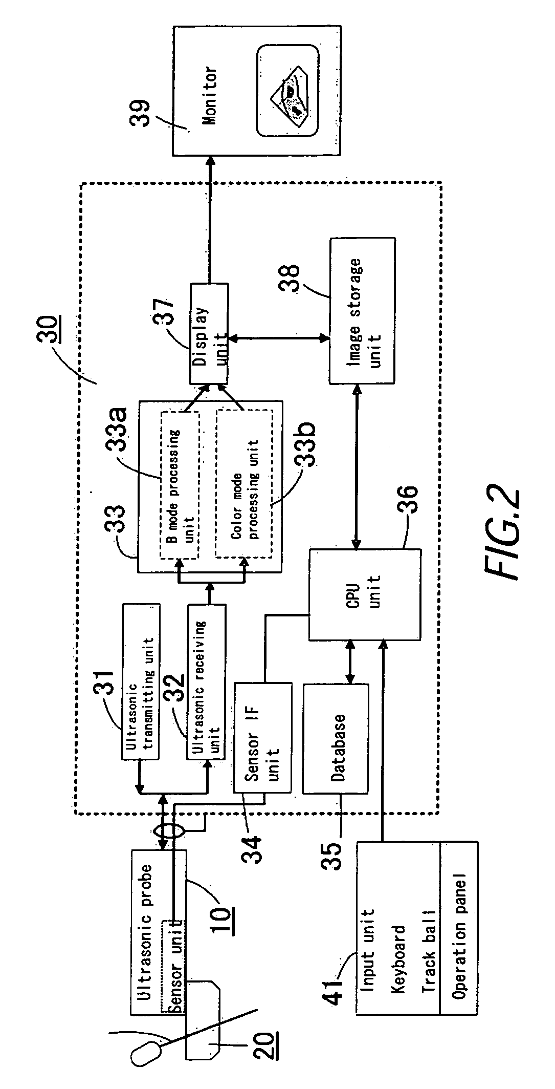
[0031] In this second exemplary embodiment, the needle guide 24 of the puncture adaptor 20 held by the probe body 11a of the ultrasonic probe 10a is moved to a desirable position. By this movement, when the stripe pattern on the slider 26 passes by the luminance element 15a and the sensitive element 15b, the sensitive element 15b receives reflected light from the luminance element intermittently. A read wire for light receiving signals is provid...
third exemplary embodiment
(Third Exemplary Embodiment)
[0037] In a third exemplary embodiment as shown by FIG. 4, a magnetized magnetic element 27a is provided on the probe body side of the slider 27 and a magnetic sensor unit formed by magneto metric sensors 16a-16f is provided at the probe body 11b in a circular direction. In the explanation of this exemplary embodiment, explanation of similarities with the first exemplary embodiment will be skipped, and differences will be mainly explained.
[0038] In this exemplary embodiment, the needle guide 24 of the puncture adaptor 20 held by the probe body 11b of the ultrasonic probe 10b is moved to a desirable position. By this movement, when the magnetic element 27a on the slider 27 passes past the magneto metric sensors 16a-16f, the magnetic metric sensors 16a-16f detect the passing of the magnetic element 27a in turn. A read wire for detecting signals is provided in the probe body 11a and the probe cable, and the signal is delivered to the sensor IF unit 34. When...
PUM
 Abstract
Description
Claims
Application Information
 - R&D
- Intellectual Property
- Life Sciences
- Materials
- Tech Scout
- Unparalleled Data Quality
- Higher Quality Content
- 60% Fewer Hallucinations
Browse by: Latest US Patents, China's latest patents, Technical Efficacy Thesaurus, Application Domain, Technology Topic, Popular Technical Reports.
© 2025 PatSnap. All rights reserved.Legal|Privacy policy|Modern Slavery Act Transparency Statement|Sitemap|About US| Contact US: help@patsnap.com