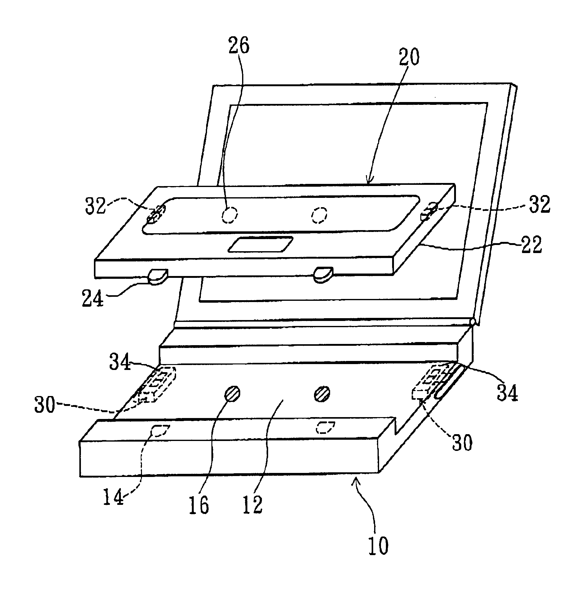
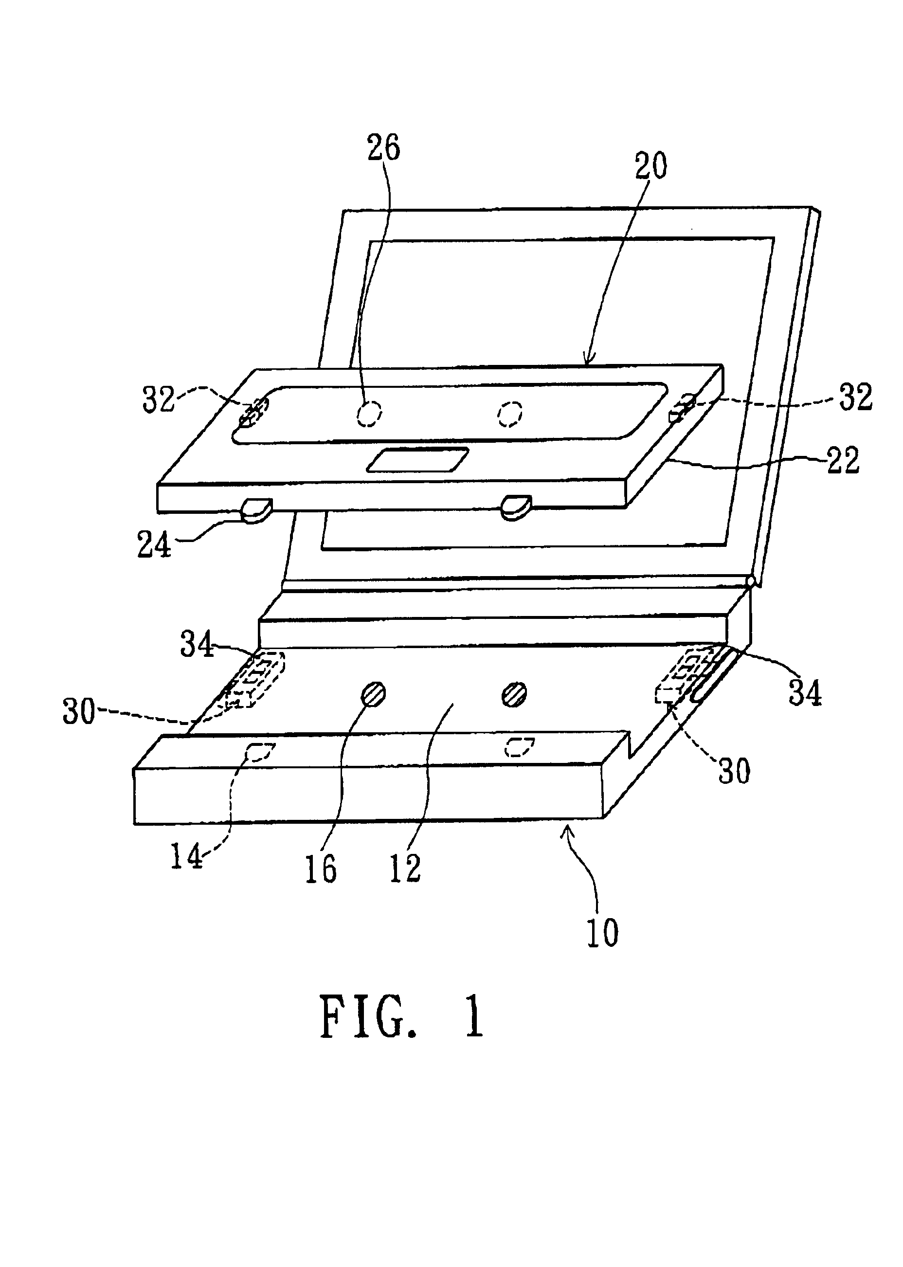
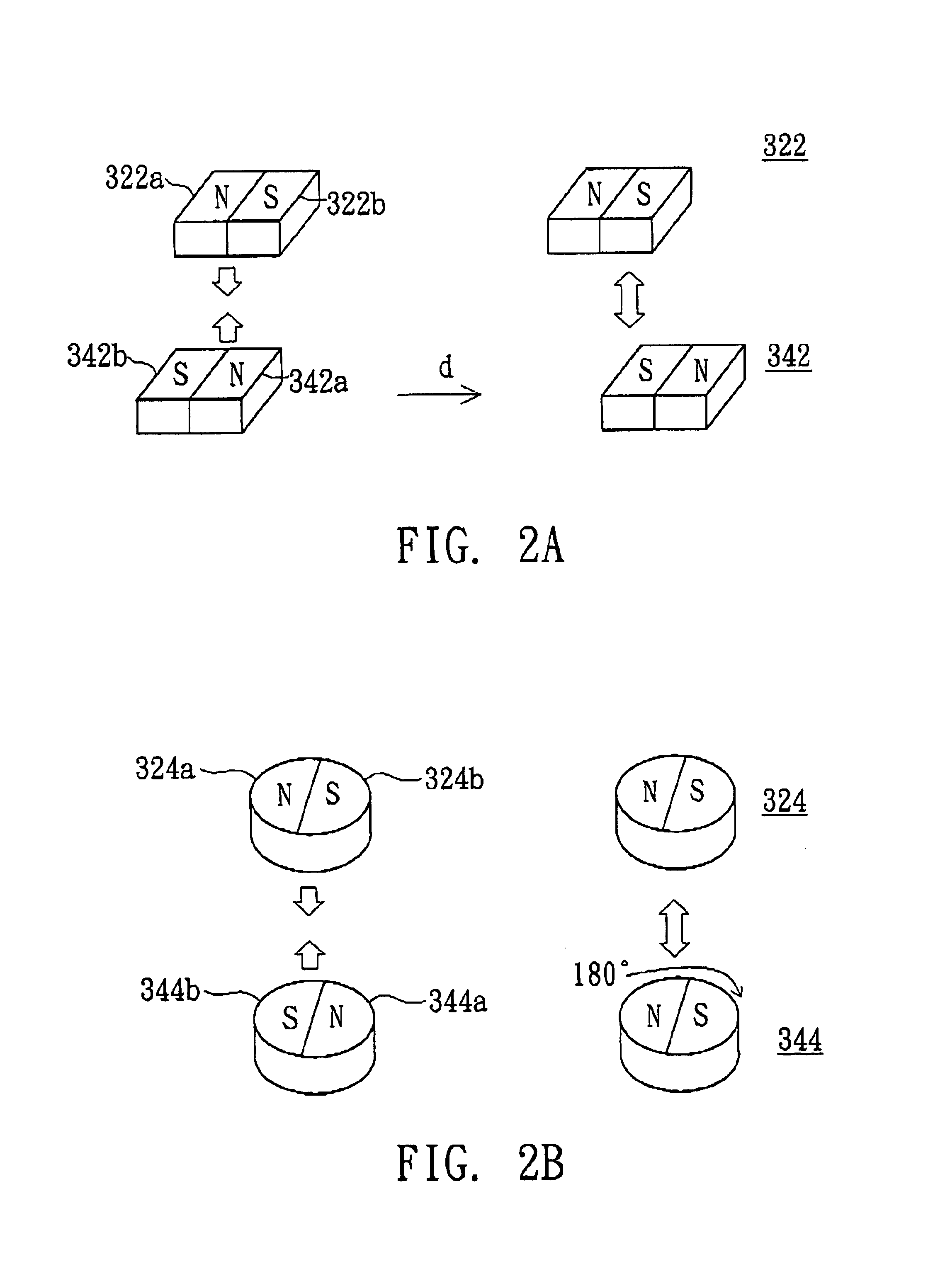
Detachable keyboard structure
a keyboard and keyboard technology, applied in the field of detachable keyboard structures, can solve the problems of limited computer housing design, uncomfortable user operation of laptop computers, fixed keyboards that cannot be adjusted by users, etc., and achieve the effect of convenient attachment and removal
- Summary
- Abstract
- Description
- Claims
- Application Information
AI Technical Summary
Benefits of technology
Problems solved by technology
Method used
Image
Examples
first embodiment
[0028]FIG. 3A is a disassembled view of a shifting type movable component according to the invention. The shifting type movable component includes a carrier 310, a movable part 350 and an elastic portion 330. The carrier 310 has a receiving hole 310a for accepting the second magnetic component 342, and the movable part 350 is integrally connected to the carrier 310, as shown in FIG. 3A. The detachable keyboard structure further includes a slide rail 302 and a barrier 102 located on the main body 10 of the computer. FIG. 3B is a top view of the shifting type movable component shown in FIG. 3A. Preferably, the elastic portion 330 is a spring, wherein one end of the spring is disposed on the slide rail 302 with the other end coupled with the carrier 310. When an external force pushes the shifting type movable component, the movable part 350 coupled with the carrier 310 is forced to move along the slide rail 302. Meanwhile, the spring 330 is compressed by the carrier 310 and pushed inwa...
second embodiment
[0029]FIG. 4A is a disassembled view of a shifting type movable component according to the invention. The shifting type movable component includes a carrier 410, a movable part 450 and an elastic portion 430. The movable part 450 includes a movable arm 452, an axle hole 454 and a push arm 456. The carrier 410 has an aperture 410a for accepting the second magnetic component 342, and a diagonal slot 410b open through the carrier 410. As shown in FIG. 4A, the detachable keyboard structure further includes a slide rail 402, a barrier 104 and a fixed pivot 106 located at the main body 10 of the computer. FIG. 4B is a top view of the shifting type movable component shown in FIG. 4A. One end of the elastic portion 430, such as a spring, is disposed on the slide rail 402, and the other end is coupled with the carrier 410. The push arm 456 of the movable part 450 has a projecting pin 458 for movably mating with the diagonal slot 410b of the carrier 410. The axle hole 454 of the movable part ...
PUM
 Abstract
Description
Claims
Application Information
 - R&D
- Intellectual Property
- Life Sciences
- Materials
- Tech Scout
- Unparalleled Data Quality
- Higher Quality Content
- 60% Fewer Hallucinations
Browse by: Latest US Patents, China's latest patents, Technical Efficacy Thesaurus, Application Domain, Technology Topic, Popular Technical Reports.
© 2025 PatSnap. All rights reserved.Legal|Privacy policy|Modern Slavery Act Transparency Statement|Sitemap|About US| Contact US: help@patsnap.com


