Sensor module for a probe head of a tactile coordinated measuring machine

a technology of coordinate measuring machine and sensor module, which is applied in the direction of electrical/magnetic measuring arrangement, measurement device, instruments, etc., can solve the problems of difficult to determine the deflection in the z direction in such measurement scenarios, considerable difficulties in scanning measurement process, etc., and achieve the effect of high accuracy and easy replacement of the sensor modul

Inactive Publication Date: 2007-11-20
CARL ZEISS IND MESSTECHN GMBH
View PDF12 Cites 105 Cited by
  • Summary
  • Abstract
  • Description
  • Claims
  • Application Information

AI Technical Summary

Benefits of technology

[0007]Against this background, it is an object of the invention to provide for a sensor module for use in a probe head of a coordinate measuring machine, which allows to carry out scanning measurement processes more easily and more accurately.
[0008]It is another object to provide for a probe head for a tactile coordinate measuring machine, which facilitates scanning measurements on a measurement object, even if the measurement object is very small and a high measurement accuracy is desired.

Problems solved by technology

However, there are still considerable difficulties in scanning measurement processes, i.e. measurement processes in which the probe head is guided in continuous contact with the measurement object (what is referred to as “scanning”).
It is still very problematic to determine the deflection in the Z direction in such measurement scenarios, despite the matching of the bending stiffnesses already achieved so far by means of the webs.

Method used


Image

  • Sensor module for a probe head of a tactile coordinated measuring machine
  • Sensor module for a probe head of a tactile coordinated measuring machine
  • Sensor module for a probe head of a tactile coordinated measuring machine

Examples


Embodiment Construction

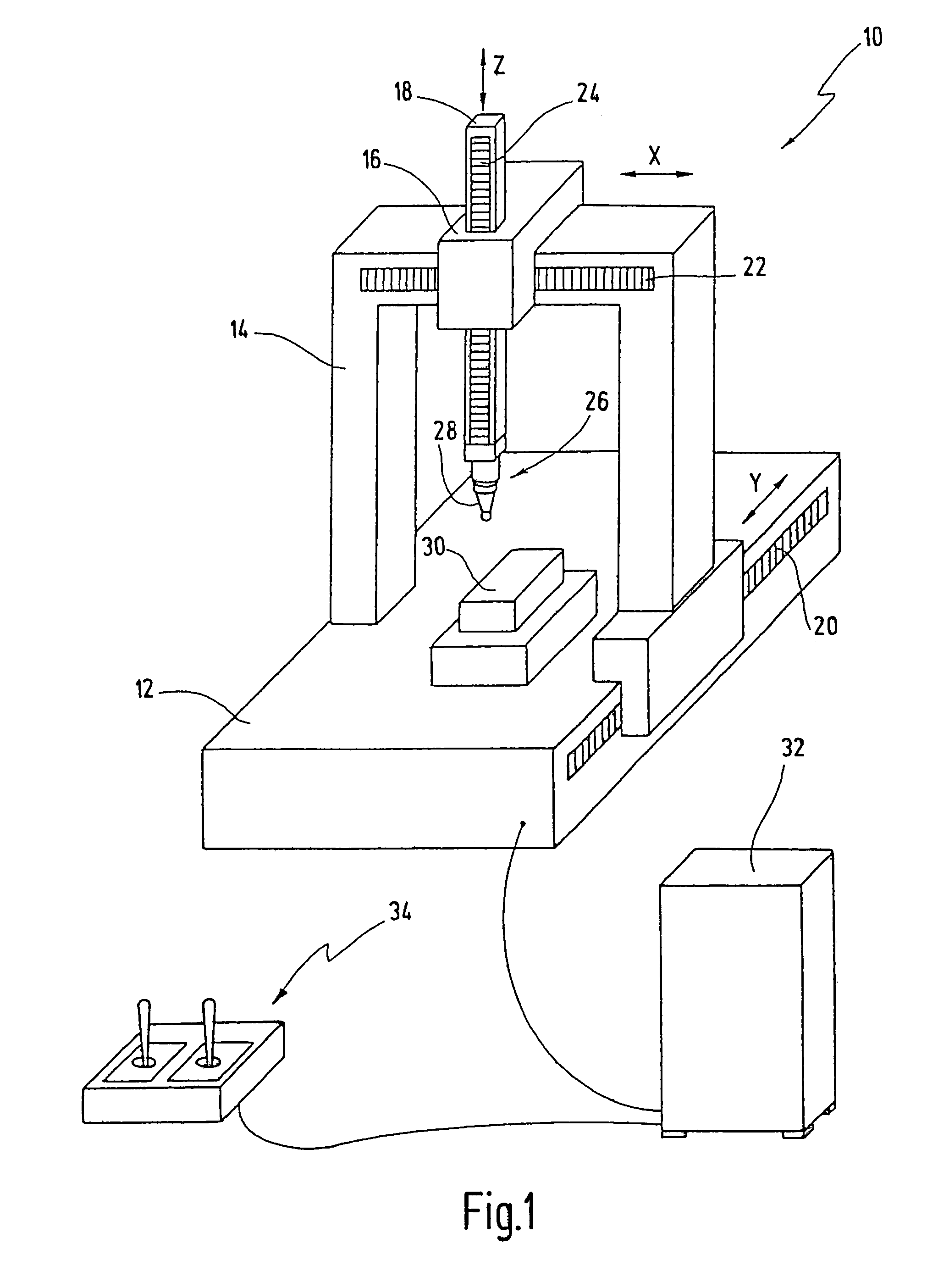
[0050]In FIG. 1, a coordinate measuring machine is designated in its totality by reference number 10. The coordinate measuring machine 10 is illustrated here in the form of a gantry structure, as is typical with many coordinate measuring machines. However, the present invention is not restricted to this form. In principle, the novel sensor module can also be used with other configurations, such as with horizontal-arm measuring machines. It is particularly preferable for the novel sensor module to be used with a coordinate measuring machine as is described in prior international patent application WO 2005 / 100906 A1, which is incorporated by reference.

[0051]This preferred coordinate measuring machine has a movement mechanism for the probe head which differs from the conventional designs and whose fundamental principle is also described in a dissertation by Marc Vermeulen entitled “High Precision 3D-Coordinate Measuring Machine”, which can be obtained using the ISBN number 90-386-2631-...


PUM


Abstract

A sensor module for a probe head of a tactile coordinate measuring machine has a frame forming a stationary module base, thereby defining a first measurement plane. A moving part is connected to the frame via webs. Each web has a thick-material web portion arranged between two thin-material web portions, if seen in a cross section perpendicularly to the first measurement plane. The thick-material web portion has a material thickness greater than the corresponding material thickness of the thin-material web portions.

Description

CROSS REFERENCES TO RELATED APPLICATIONS[0001]This application is a continuation of international patent application PCT / EP2005 / 005622, filed on May 25, 2005 designating the U.S., which international patent application has been published in German language and claims priority from German patent application De 10 2004 037 490.2, filed on Jul. 23, 2004. The entire contents of these priority applications are incorporated herein by reference.BACKGROUND OF THE INVENTION[0002]The present invention relates to a sensor module for a probe head of a tactile coordinate measuring machine, and to a probe head comprising such a sensor module and a stylus attached to the sensor module.[0003]In the prior art, coordinate measuring machines are used inter alia for measuring the shape of a measurement object with high accuracy. For example, the shape of workpieces produced by machine may be checked in this way in the course of quality control. For the measurement process, the probe head of the coordin...

Claims


Application Information

Patent Timeline
Patent Type & Authority Patents(United States)
IPC IPC(8): G01B5/012
CPCG01B7/012
Inventor SEITZ, KARLSTRAUSS, WOLFGANGROTH, ROLANDDOMINICUS, WALTER
Owner CARL ZEISS IND MESSTECHN GMBH
Why Eureka
Try Eureka